Slide Sentinel Updates
Author: Aleks Vidmantas
Show More
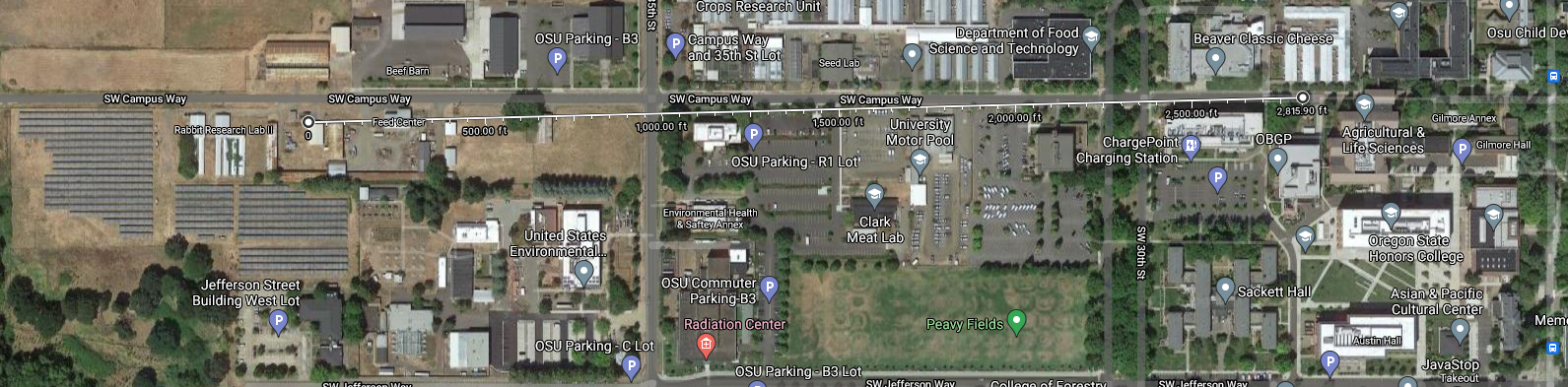
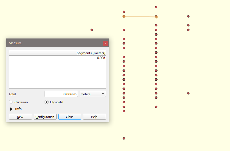
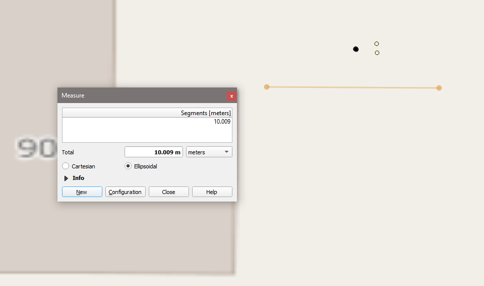
This is a brief but interesting look at how base antenna position and accuracy has cascading effects on the determined rover accuracy. At some point during this July 2022 test deployment, the antenna fell over on the base, causing RTK fixes on the rover to be worse than just the rover antenna determined location. Below is a graphic demonstrating this, with green being RTK fixes and white being just the antenna-determined location without corrections from the base.

Author: Aleks Vidmantas
Show More
The team wanted to examine how the Slide Sentinel system performed in a field environment with two rovers collecting data. Additionally, another primary goal was to examine a rovers performance in detecting 1cm increments, which is below the hardware’s 3cm hardware rating. The original document outlining goals for the experiment can be found [here](https://docs.google.com/document/d/1OrRRWbBjfaKc4W1jUN1STj2B3kDFD4FKV3C5IjADxEk/edit) . The start of official data collection took place on 4/28 and ended on 6/5. The team used 80/20 extrusion to carefully move the antenna in a linear fashion.This is the most extensive test deployment Slide Sentinel has done, with nearly 1200 data entries. The most important result from this test Slide Sentinel is able to detect 1 cm increments of movement. Additionally, some flaws were uncovered over continuous sampling. One is find the cause to rovers uploading a “null” gps value. This was due to the Piksi Swift not being fully powered and being unable to send coordinates to the feather. Additionally, if there are a lot of uploads were the gnss mode isn’t an RTK Fix, it’s likely due to either the Piksi Swift power cycling or not receiving corrections from the base. This will be shown later down below.
From 4/28 to 5/8, a stationary position was used to ensure healthy functioning of the slide System. On 5/9, a rover was moved to a rail system allowing the team to precisely move the antenna 1 cm at a time.

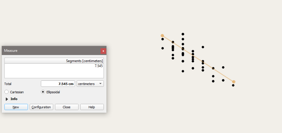
This shows the 3 clumps of data. The top two clusters represent a single rover, the right clump being sampled from 4/28 to 5/8. From 5/9 to 6/5, the rover is on the rail (top left). All RTK fix clusters were no more than 3 cm in diameter, matching hardware specifications.
Each grouping showed a standard deviation of around 0.616 to 0.702 cm. This figure is a good benchmark for healthy system performance. Below is a closeup of several groupings. Each different symbol represents a different true position for the antenna.

One important highlight with the sliding rover is that a number of data points are required before a system is able to determine 1 cm movements due to the standard spread of data points.
Author: Aleks Vidmantas
Show More
The above documentation is where the bulk of our day-to-day updates get posted at. The guide includes references to all sorts of parts on the PCBs, configuration guides, deployment guides, PCB building instructions, and more.
Author: Aleks Vidmantas
Show More
The Slide Sentinel team was invited to Fall Creek, the location where we will be deploying our equipment at. The purpose was to ensure our radios were able to communicate at range through occasional foliage and altitude differences, as well as ensuring our GNSS hardware was capable of generating RTK fixes, a necessity for deployment.
The tests occurred at approximately 1000-1400 meters from base to rover. The base had a clear view of the sky and almost direct line of sight to the rover with no obstructions on the base. The base was at an altitude of approximately 1300-1400 feet, while the rover test sites varied from 700-1400 feet. The rovers had an acceptable line of sight to the base, however, there were a notable amount of trees in the way. The GNSS antenna experienced an average of 25-65% canopy cover, with two tests being done on both extremes of clear canopy and around 75% canopy cover.
The tests consisted of simply turning on the base and rover at different locations and observing the RTK process and satellite signals. The Rover team moved the antennas in different locations to figure out optimal placements. Two sets of Rover tests were done at two locations: towards the bottom of the landslide, at the top of the landslide.
The base position is fairly optimal, with a clear line of sight to the landslide. Additionally, GNSS satellite signal strength was phenomenal. The rovers experienced relative success at all locations, however, there was a significant signal loss at antennas placed at 2 feet above the ground compared to 6-7 feet off the ground. Radio signal strength was on average -90dB compared to the radio's minimum signal strength requirement of -122dB. PDOP, or Positional Dilution of Precision was around 1.7-2.8, which is below the generally accepted measurement of 4.0 for RTK-fix capabilities. The Rovers did struggle to meet the required shared 4 shared satellites above 40dB when the antenna was only placed at 4 feet above the ground. At 6-7 feet with the best practical antenna placement regarding canopy cover, the Rover had around 10-15 satellites above the required 40dB measurement, which is more than enough for RTK capabilities.
Rover Signal at 45% Canopy around 6 feet off the ground
This field scouting trip proved that both the radio and GNSS devices are capable of generating RTK-fixes and meet the minimum requirements so long as some thought is put into antenna placement. Every rover location tested met the minimum requirements, with ones with clearer canopy cover and clearer line of sight to the base faring much better than ones with less. Additionally, all rover tests at the top of the landslide had a much easier time communicating with the base, likely due to a much smaller altitude difference.
It was discussed that a directional radio antenna mounted on the base would greatly increase radio strength. The main benefit would be to accommodate rovers placed at vastly different altitudes. The angle between the highest rover, lowest rover, and the base is well within 35 degrees. The somewhat precarious radio strength may make any tests at distance with 2.4 GHz radios require directional antennas on the base.
Author: Aleks Vidmantas
Show More
The team tested out the Z9 radios in an attempt to measure the maximum range of our radios with Omni-directional antennas. The Z9's noise floor is -128dB. With the use of adapters and long cables, it could be slightly lower at potentially -122dB, but this is not currently measurable and is a guess.
 We were able to get 100% reliable communication at 2815 feet with a signal of -90dB with LOS. Another site was tested exactly 1 mile but there were a number of obstacles like electrical wires and heavy tree foliage, and communication was unreliable.
The team tested out the European 2.4 GHz radios in a full deployment for 1 day. We reduced the time delay from 15 minutes to 5 to get as much data as possible in 14 hours. Out of 54 uploads, 53 were RTK fixes, however, the precision is only 4 decimals due to a mistake regarding Platform IO values uploaded. The team originally thought that changing the negative exponential would be enough but setting Platform IO to also use the DOUBLE value is also 100% necessary.
The team also wanted to see if setting the negative exponent to -10 would fix the difference in spacing between x and y seen below, but again due to the absence of the USE_DOUBLE header, this was not possible.
(Note: this data is from a previous deployment and is meant to represent the spacing issue between x and y)
Bad: {"GNSS":["[4,2162,265057200,44.56641096,-123.2935674,55.67718816,15,193,88,161,107,135]"]}
Good: {"GNSS":["[4,2170,299598200,44.5664,-123.2936,54.24417,15,168,79,146,83,122]"]}
- Trial-Proven 2.4GHz radios that can be used for deployment.
- First 100% representation of a rover that will be delivered to a client with proper mounting hardware and soldered connections.
- 98% RTK Fix Rate, albeit unfortunately with no usable data due to the precision mistake.
- The expected 54 RTK fixes that match up with a 5-minute sleep/10-minute wake cycle over 13-14 hours.
- Testing of new SD code that has the proper time but unfortunately fails to increment.
Parts have been handed out to a teammate and construction is underway.
Author: Aleks Vidmantas
Show More
The team has decided on the GXM-T14 Radios by Freewave. These radios have identical pinouts to the Z9-T/C radios, allowing immediate drop-in replacements for use in the EU. These operate around 2.4ghz and feature TTL communication, which our PCBs are capable of dealing with. The configuration for these radios is slightly different but still compatible with the Z9-T/C devkits.
The radios were successfully made to communicate with each other. The radios must be in point-to-multipoint mode in order to use a network ID. Otherwise, a call book system needs to be used.
Author: Aleks Vidmantas
Show More
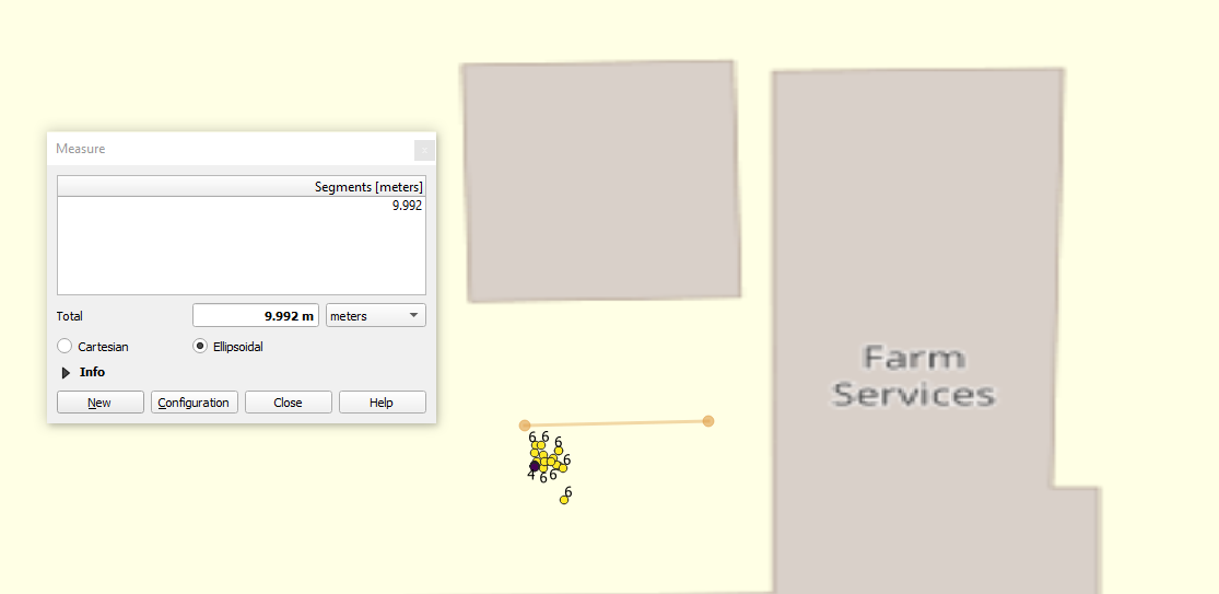
Slide Sentinel had its first multi-rover deployment success. The data below is from a two-day deployment.
 Unfortunately, the antennas were accidentally not mounted so there were only a few hours of good data, as indicated by the wide spread of data for the top left rover.
A team member was also able to potentially salvage 2 rovers and a base. Both rovers suffered mechanical faults from previous tests and were considered destroyed. After some soldering, the rovers passed initial testing.
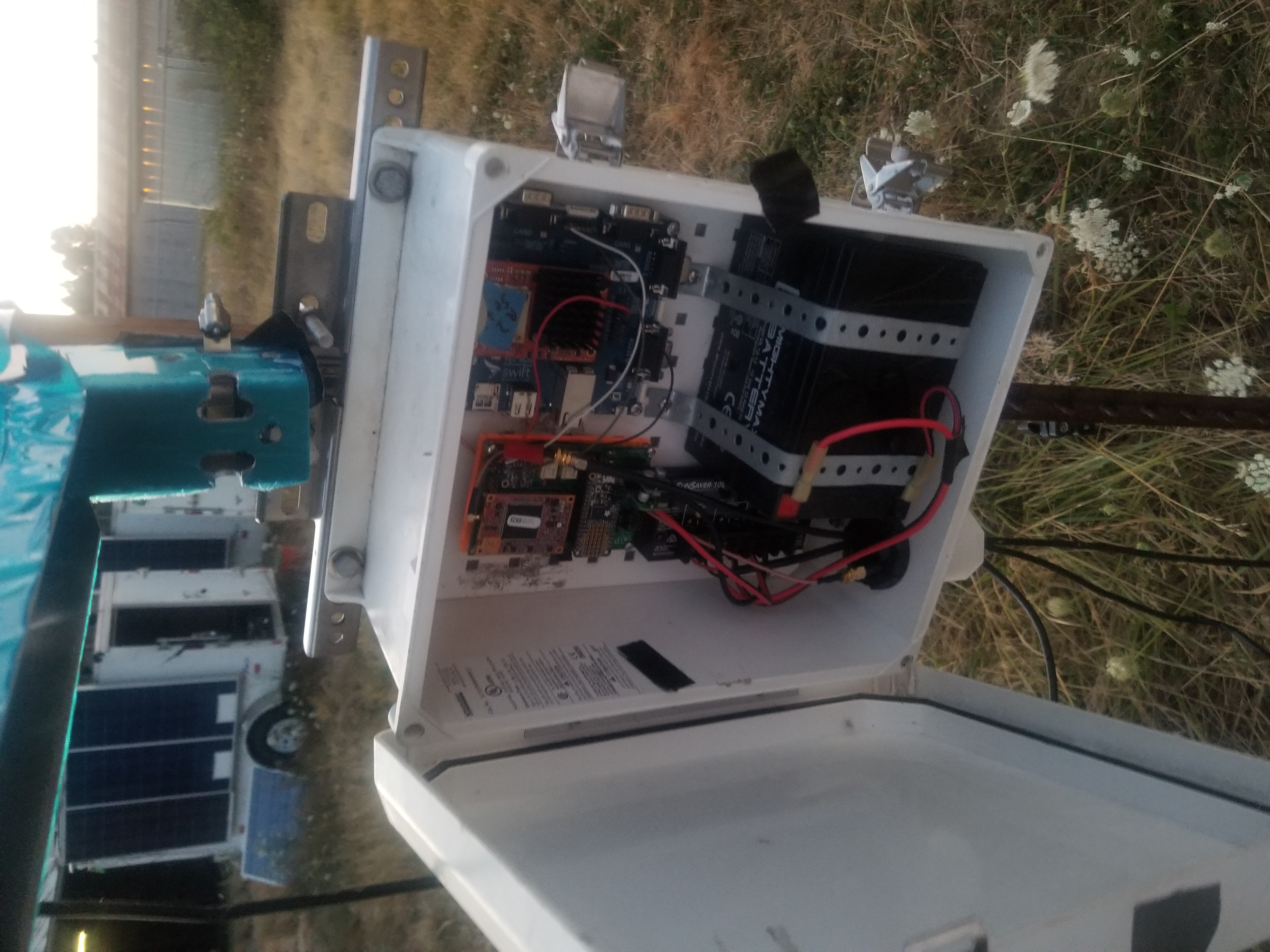
The antenna housing is a simple L-bracket like one used to hold up a bookshelf. Two holes in the horizontal piece allow the GNSS and Radio antenna to be mounted via washers over the SMA cable's threading. It is attached to a post via a U-bolt.
The hardware is incredibly close to being in a state to be delivered to share holders and is unlikely to change. Rugged attachments have been designed for the PCBs and loose wires are soldered to improve hardware reliability. The only hardware shortcoming is that a rugged solar panel attachment is lacking. Code-wise, there are several optimizations that aren't in place quite yet, but these changes only need to be deployed to the base.
Author: Aleks Vidmantas
Show More
The team has done a deep dive into the ins and outs of our Radio Telemetry system due to a myriad of issues encountered with it recently. This is after a several-week deployment at the CTEMPS field. The main issues we encountered are:
- Bad PCB radio connection - The 14-pin female radio terminal on one of the PCB's was torn off after standard removal of the radio.
- Questionable 14-pin connection - The team should look into a more reliable or higher quality terminal block for the Rover and Base PCB, as occasionally some of the radio pins wont make contact with the slots.
- RPSMA and SMA confusion - For general information, follow this link. Since November, the team has been using a Male RPSMA antenna hooked up to a cable that is Female SMA. There is not male pin in either of these connections, giving the false impression that the radios were using the antennas when instead, all communication was directly from the MMCX connector on the radio itself. This explains why moving the rover closer to the base greatly improved connection strength, as well as why, during previous radio testing, the team was only able to maintain connection up to 30 feet. To remedy this issue, a Male SMA to Female RPSMA adapter should be used. This should greatly increase system reliability for future deployments.
- MMCX mating cycles - The MMCX standard connection has a finite amount of times it can be mated, with estimates between 5-500 depending on the disengagement force. The team has already made it a practice to leave the MMCX connections on the GNSS/Radio due to a damaged component earlier this year, however careful examination should be taken for future deployments to ensure stable connection during deployments.
Author: Aleks Vidmantas
Show More
The Slide Sentinel team deployed at CTEMPS on March 19, 2021. So far, we are still ironing out setup issues, but there were some important findings:
- The radios must be placed at equal height or have their "dome" of influence intersecting by angling the antennas into each other. Below is an image that best illustrates this.

-
Jumper cables wear out very quickly after frequent testing. It was discovered that even though a power cable was connected to the GNSS board, the board would enter a continuous reboot phase since the connection wasn't strong enough. This has been an issue before, but when first deployed, everything was working, so the likely theory is that while we were exiting the trailer to leave, the movement alone could have been responsible for the initial failure.
-
RTK fixes take a remarkably short time (1-2 minutes) in clear weather. There is an automatic 10 minutes allocated for RTK fixing by default since it can take up to that long to secure a fix during cloudy weather.
-
No second upload, still working on this. I (Aleks) plan on going down today to see what it is.
-
The GNSS makes a whining noise when the solar panel of the base is plugged in, this may be normal.
-
Jumper cables are a less than ideal solution causing many problems, reducing reliability.
-
There is another Base/Rover set that has been successfully deployed in a home environment. The goal is to get it ready for field testing as soon as possible.
-
Long-range testing of radios - due to the initial troubles we had with the antennas communicating with each other, it is vital to ensure they can work in a forested environment at a distance.
-
Multi-rover trial run - it is also critical we test a multi-rover constellation, which works on paper but hasn't been tested recently.
-
Elimination of jumper cables - due to the number of issues we've received from jumper cables, the team has decided to try to implement barrel jack connectors for GNSS power, along with a solution for data cables like JST.
Author: Aleks Vidmantas, Cyrus Swihart
Show More
| Statistic | Value | Delta |
|---|---|---|
| Entries in Datasheet | 79 | NA |
| Number with complete GPS | 68 | NA |
| Number of complete GPS fixes | 64 | NA |
| Number of GPS fragments | 4 | NA |
| RTK Fix Rate of complete GPS Logs | 94.1% | +1.5% (Good) |
| Overall RTK Fix Rate of all transmission | 86.1% | +14.1% (Good) |
| SD of 64* RTK Fixes | 2.26 cm | +1.16cm (194% increase, Bad) |
This analysis took place over only 2 days, with data coming in much more rapidly. Differences include:
- 10 minute wake time, 15 minutes sleep time. Goal being to get more data points in the span of a shorter time.
- Removed back-off counter. This means that if a handshake request fails, the rover will fall asleep for its normal time rather than doubling its sleep time.
- SD fail guards on the rover. If for whatever reason the SD card does not initialize, then it will not prevent the rover from functioning.
I am hesitant to draw any immediate conclusions, but the RTK Fix Rate of all transmissions, while immediately not too important, objectively improves the efficiency of the RockBLOCK Line rental. There isn't enough long-term data to determine standard variation in these statistics. This analysis is temporary and the deployment is ongoing.
Overall, the deployment has gone well so far. There were a few issues as I was getting the system started, but it seemed to be a problem with a loose connection on a jumper wire powering the GNSS board (We have experienced this issue before). Snowfall has delayed the deployment, but I will get the system running in no time.
Below are the graphical images of the data points.
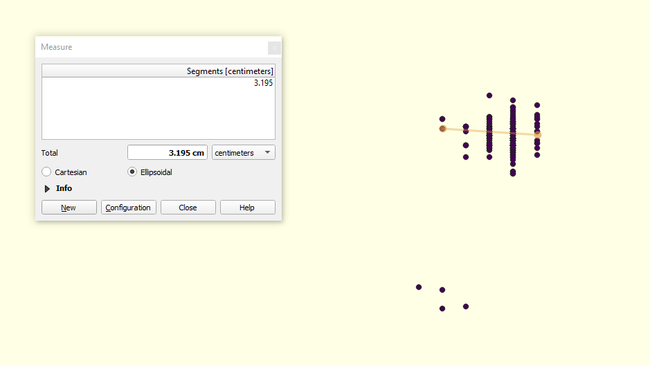
The dark purple points are RTK fixes
A closeup of the RTK fixes, SD of 2.26cm
Author: Aleks Vidmantas, Cyrus Swihart
Show More
Tasks Completed
- Fixed the Wiki so images show due to a mistake on my part of deleting old repositories. The code is backed up and also exists on the main branches. I plan on moving them back to a Slide Sentinel Branch soon.
- Found out that a loose radio tx pin could be the issue, diagnosed with the oscilloscope with the help of Isaac, not confirmed. Isaac recap of time spent on the radio
- Performed rudimentary data analysis on the October-November deployment
- Performed rudimentary data analysis on Cyrus's 2-Day deployment
- Assembling a replacement PCB for the Thanksgiving Base. Currently missing a multiplexer, searching for it, misplaced in the transfer of parts.
- Coordinating with Shumway about potentially receiving help regarding radio
- Made aware by Cyrus of PostProxy issues regarding transferring data from RockBLOCK to Google Sheets. On the backburner as I wrote a script that gets everything important.
- Deployed the rover and base in my backyard for testing on Tuesday. The system was running with 10 minute wake time, 15 minute sleep times. Due to snow (Currently ~2 inches), I have decided to unplug the system yesterday (Thursday 2/12). I need to go to home depot and buy some putty to close up openings on the casing where wires go through. I do not want to risk water damage. It is my main objective to safely redeploy the system and start collecting data.
- I am working on a deployment document detailing the events for the current deployment.
- Moving forward, I am going to finish documentation of the code I started a while back. Knowing I am transitioning out of the lab, I want to make the code more understandable for other people. Additionally, I will update Aleks' Uber guide with any information I find necessary.
- I have completed SD guards for the rover, but I will add SD guards for the base code this week. This will help Aleks test his system since his SD card holder seems to be faulty.
- Progress regarding the Thanksgiving set is painfully slow, due to collisions of work time between Isaac and myself (Aleks) and organization. I've started assembling an inventory of all parts required for the PCB and am only missing one part (multiplexer IC). If I can't find it today I'll order one to make sure headway is made. Additionally, a faulty SD card holder has greatly slowed testing.
- There is some fallout from deleting stale branches that I've been cleaning up recently. Images are fixed on Wiki and in the future, I'll ensure repositories are labeled for their designated use. I still need to write a replacement/redeploy PostProxy.
- I've been learning QGIS and have made progress analyzing data. Future data analysis should take less than 30 minutes. These statistics can be used to benchmark future deployments. Gantt Chart
- The number one goal has shifted to assembling another Base PCB. Once inventory is complete, manufacturing can begin immediately with Isaac and I (Aleks).
- When not working on the PCB, the goal is to further test the broken one after either replacing the SD card holder or Cyrus's new code that error handles the SD Card. Potentially help from Shumway may yield a solution.
- Additionally, I (Aleks) need to move all the images in the wiki to a labeled repository, as well as make sure the RockBLOCK -> Sheets pipeline is back at 100%.
| Statistic | Value |
|---|---|
| Entries in Datasheet | 225 |
| Number with complete GPS | 175 |
| Number of complete GPS fixes | 162 |
| Incomplete due to Accel. Log | 30 |
| Number of GPS fragments | 20 |
| RTK Fix Rate of complete GPS Logs | 92.6% |
| Overall RTK Fix Rate of all transmission | 72% |
| SD of 160* RTK Fixes | 1.11 cm |
The dark purple points are RTK fixes
Here you can see the two groups of RTK fixes. The second, smaller group, represent RTK fixes that occurred at the very end of the deployment, leading to potentially skewed data, so it was not included in the SD statistic.
The second group of RTK fixes is likely from when we realized that the time intervals were sporadic so we interacted with the rover, likely physically moving it a little bit.
This data shows that the RTK fixes are incredibly accurate, with a standard deviation of only 1.1cm. Our main priority for future deployments is to ensure data upload reliability. The main causes are:
- A programmed back-off timer causes the Rover to sleep for 3 times its set sleep time. Cyrus has done some testing with the first set with a programming fix and the removal of this back-off timer has greatly improved the upload rate of the rover.
- Unreliable handshakes with the radio. This is likely a programming issue as all testing with radios in their dev kit has shown that the radios rarely if ever fail to communicate.
Authors: Cyrus Swihart, Aleks Vidmantas, Isaac Goshay
| PCB | Accelerometer | GNSS | Radio | SD Card | |
|---|---|---|---|---|---|
| Rover 1 | OK | ||||
| Rover 2 | OK | OK | OK | OK | OK |
| Base | OK | N/A | OK | OK | OK |
| PCB | Accelerometer | GNSS | Radio | SD Card | |
|---|---|---|---|---|---|
| Rover 1 | OK | OK | OK | OK | OK |
| Base | UNKNOWN | NA | OK | UNKNOWN | FAULTY |
| PCB | Accelerometer | GNSS | Radio | SD Card | |
|---|---|---|---|---|---|
| Rover 1 | |||||
| Rover 2 | |||||
| Base |
Another feature I implemented was a macro called SATCOM_ENABLE. This can be set to TRUE or FALSE and was implemented to make testing easier. If the value is set to FALSE, then none of the code involving the Rockblock+ module will be ran. Previously, if we forgot to comment out Satcomm controller code while testing with an inactive Rockblock+ then the base would fail to initialize.
Things to improve on with the next deployment would be to make sure that we are able to more consistent. The system was out for more than a month and we were only able to get a good two week stretch. in order to improve we would need to make sure that our battery is fully charged or to get a new battery that can power the base for two or three weeks without being recharged. The calculations for the new battery has been done and will be verified soon.
The write up concerning the deployment and updates for the stakeholders is still being made. I still need to add more information from the meeting with Cara. The idea is to lay out what we have so far in terms of functionality, expectations from the system, and our current set up / specs. Also to add our goals for the next deployment also to ask more about what they are expecting from this project.
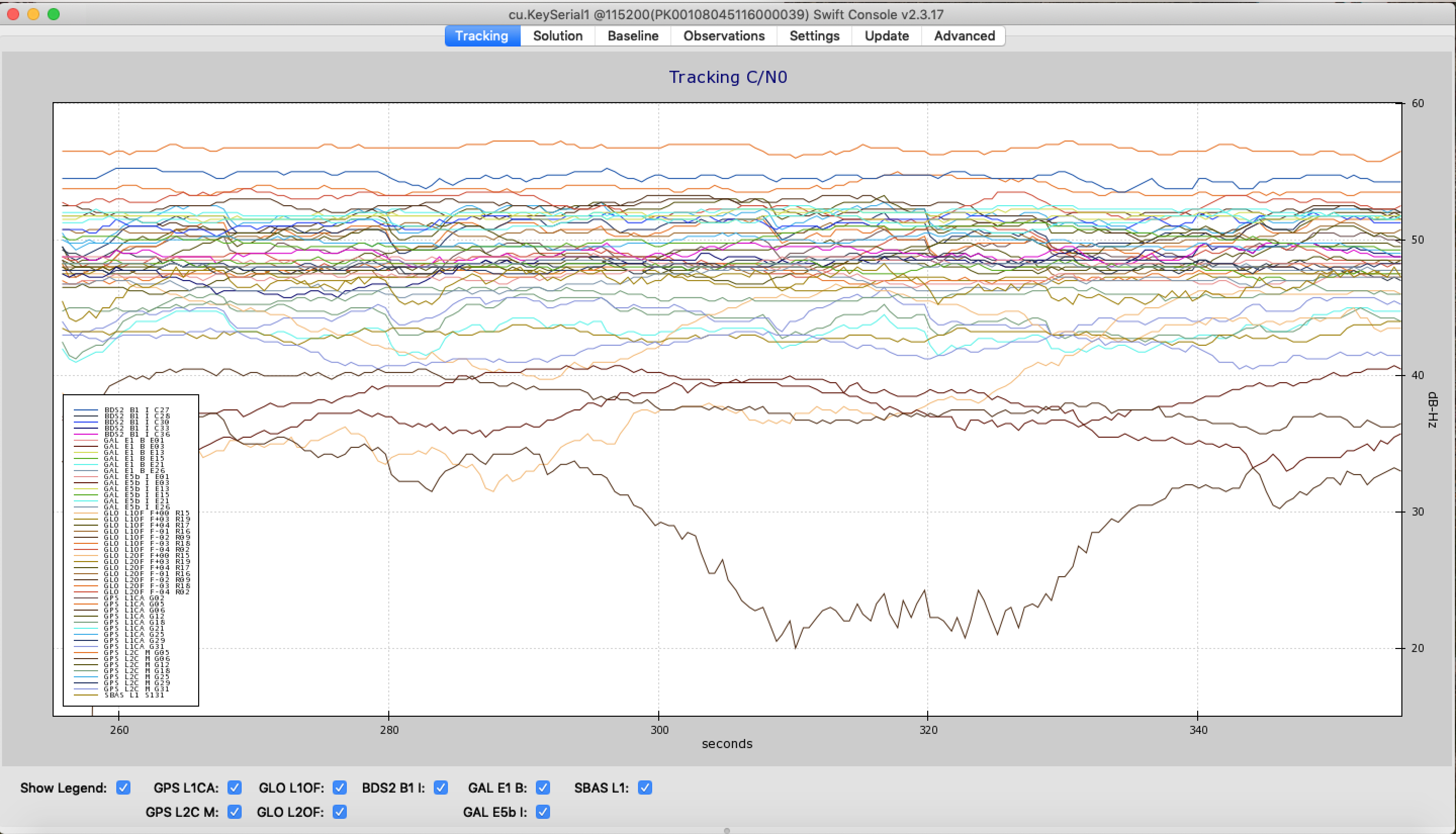
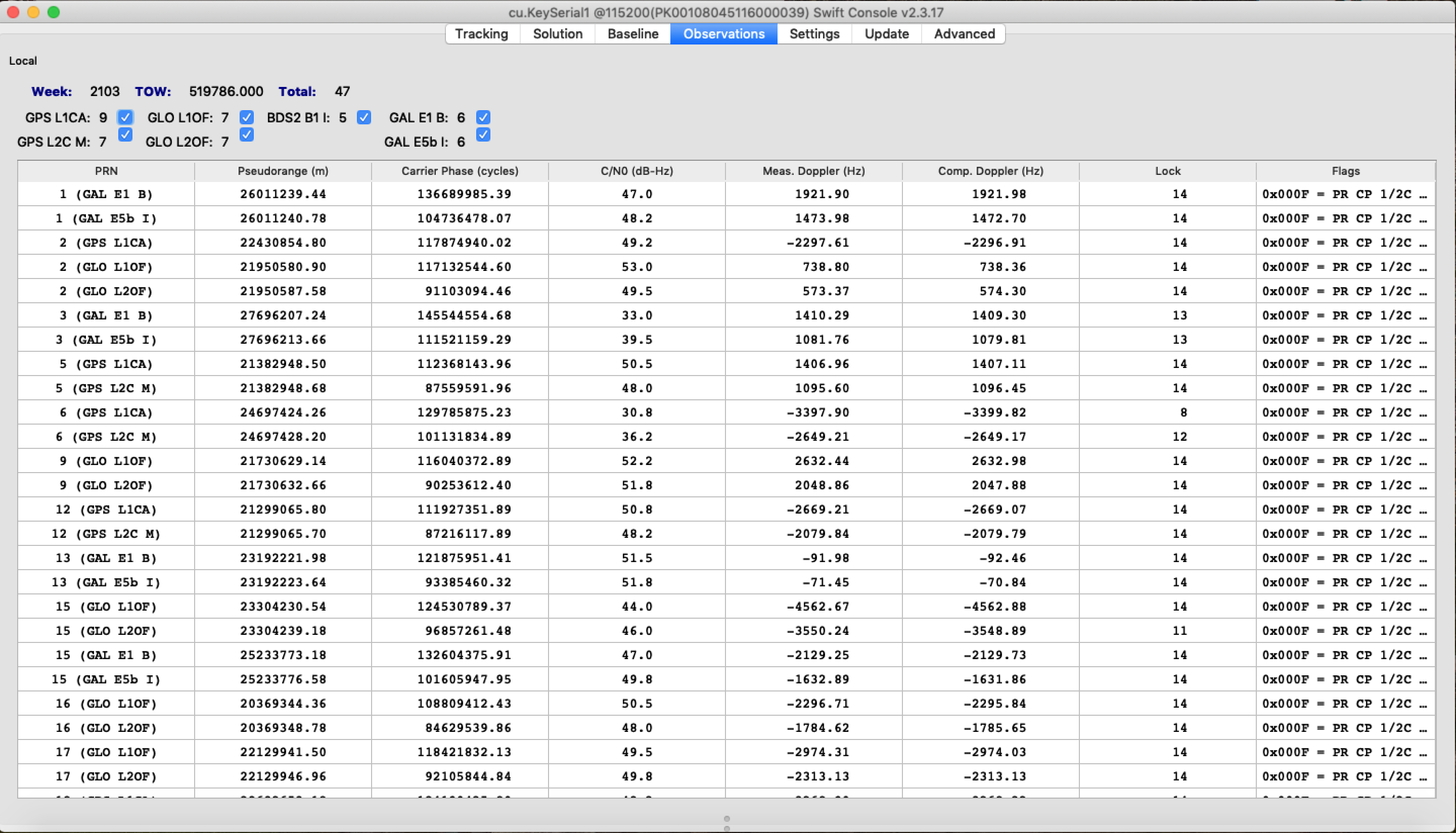
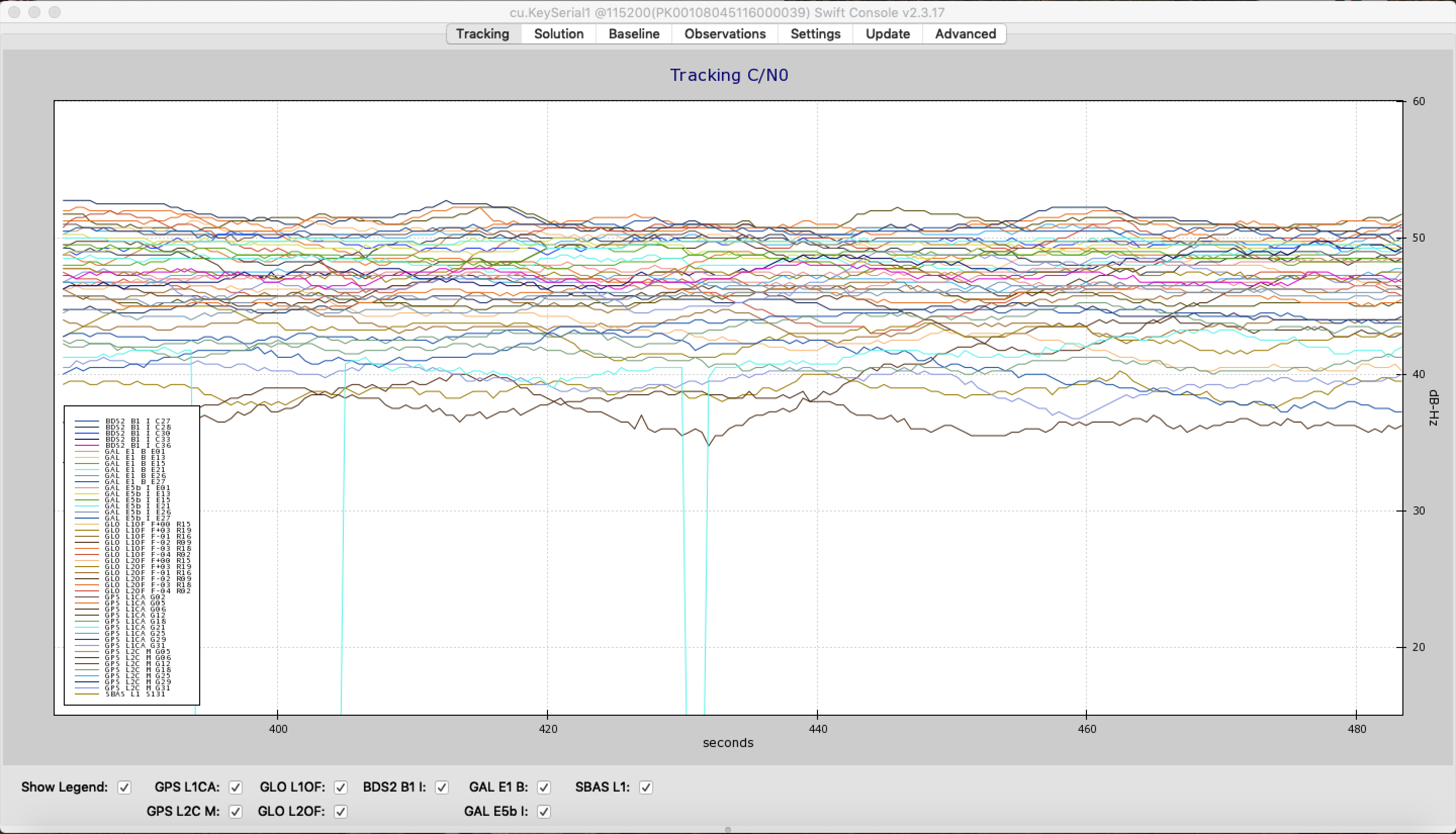
The 2nd Base/Rover set is nearly complete however there is a radio communication issue that prevents the Rover from handshaking with the Base. Both radios work perfectly when in the Dev Kit, and the Rover does send the handshake to the Base radio. The issue lies somewhere along the communication pipeline between Base Radio and the Base Feather. At first, I thought the issue was related to the selection of the Z9-T as the base radio rather than the Z9-C, since the T has never been used as a Base. After updating and configuring a Z9-C, the exact same error appeared: "No ACK from Server".
.png)
By attempting to read the raw serial data at the correct baud rate (115200), the issue can be narrowed down to physical, or software. If communication does get through, the issue is software related, if not, hardware.
This issue has prevented a deployment of the second set so it is crucial that it is solved immediately. After this is fixed, a short 1-day test of wall-powered deployment will commence, and if successful, a 2-week field deployment can take place immediately after.
Author: Kamron Ebrahimi
Show More
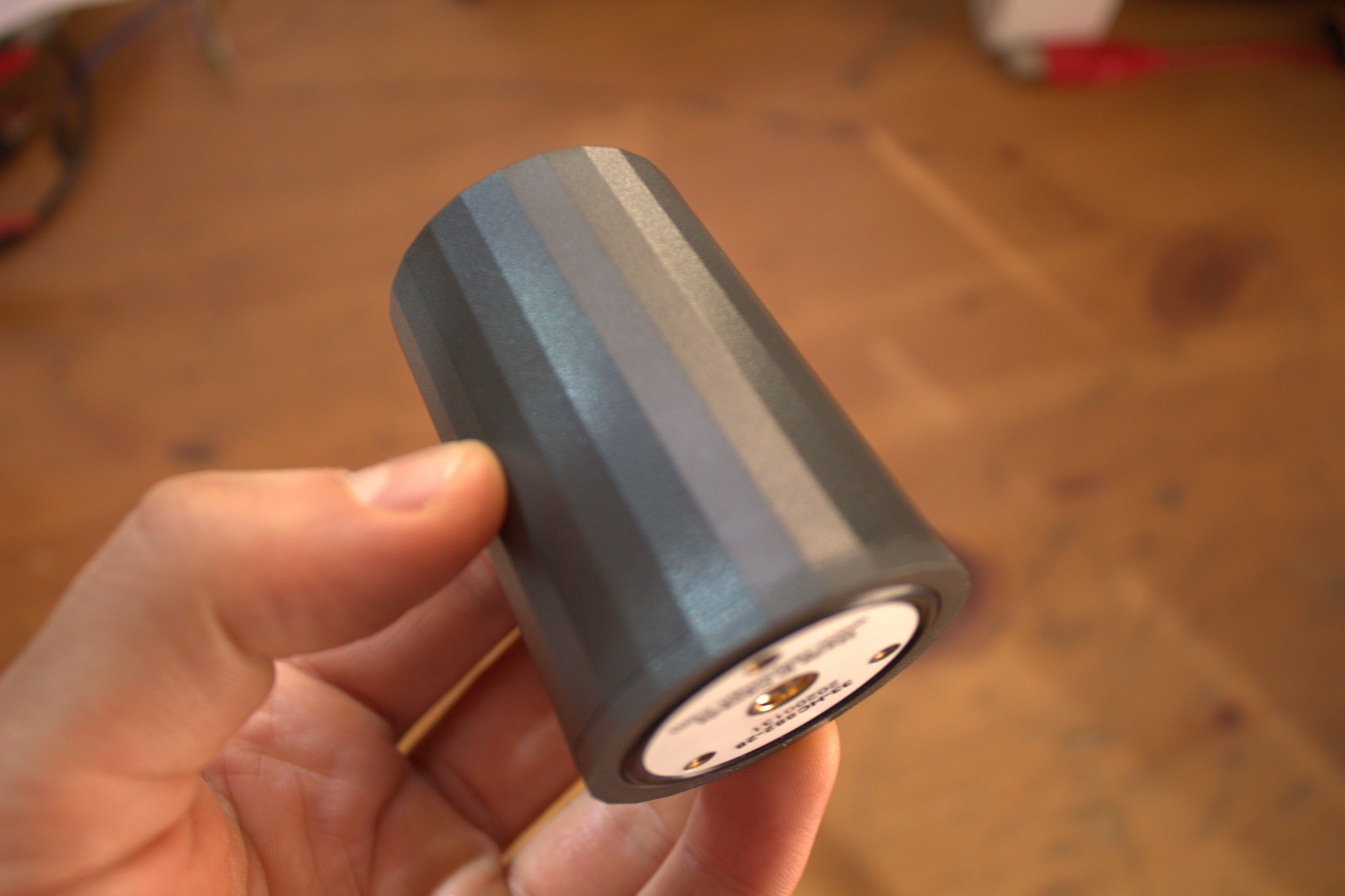
Last month the team purchased components for 2 new rover's and new base station. As part of this purchase we needed some new GNSS antennas. GNSS antennas can be extremely expensive and easily reach several thousand dollars for triple frequency reception survey grade quality.
This past Winter at the AGU 2019 Fall Meeting I had the pleasure of speaking with the folks at Tallysman, a high end precision GNSS antenna manufacturer based in Canada. The representatives took great interest in Slide Sentinel and were experts on GNSS. We purchased three of their 33-HC882-28 triple-frequency GNSS antenna for the new units and this past week I finally had time to take them out for a test and compare them against the antenna we've been using, the Tersus AX3702.
Several factors contributed to our purchase of these new antenna. The first is their competitive price for a triple frequency antenna at ~$250 on DigiKey. One of the overarching design goals for the Slide Sentinel rover is to make the unit as small and portable as possible. These antenna have the perfect form factor and weight for our desired design. They weigh a mere 42g compared to the Tersus' 374g. Additionally should a Slide Sentinel be needed for forested environments having triple frequency GNSS support is ideal.
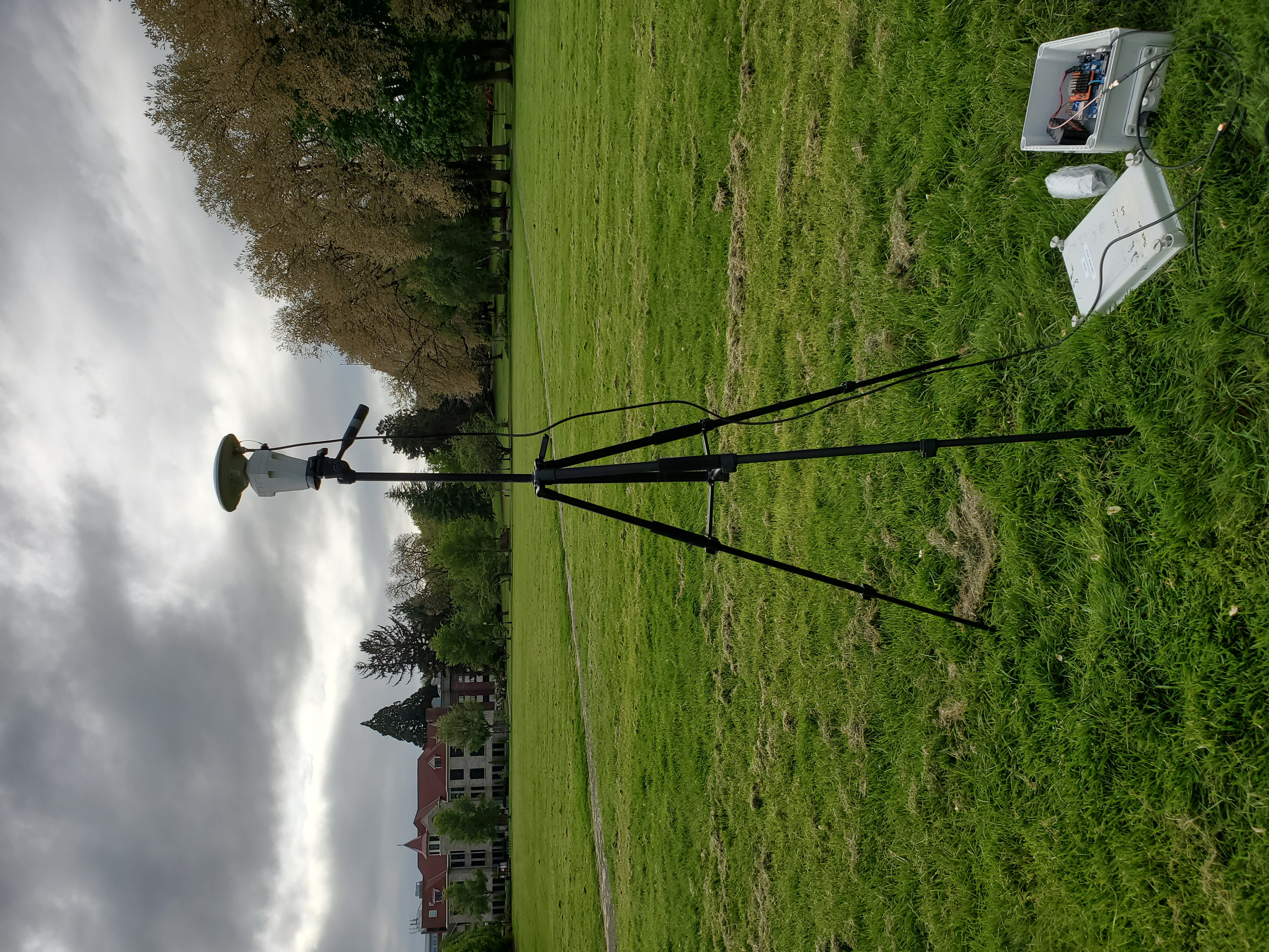
| Setup |
|---|
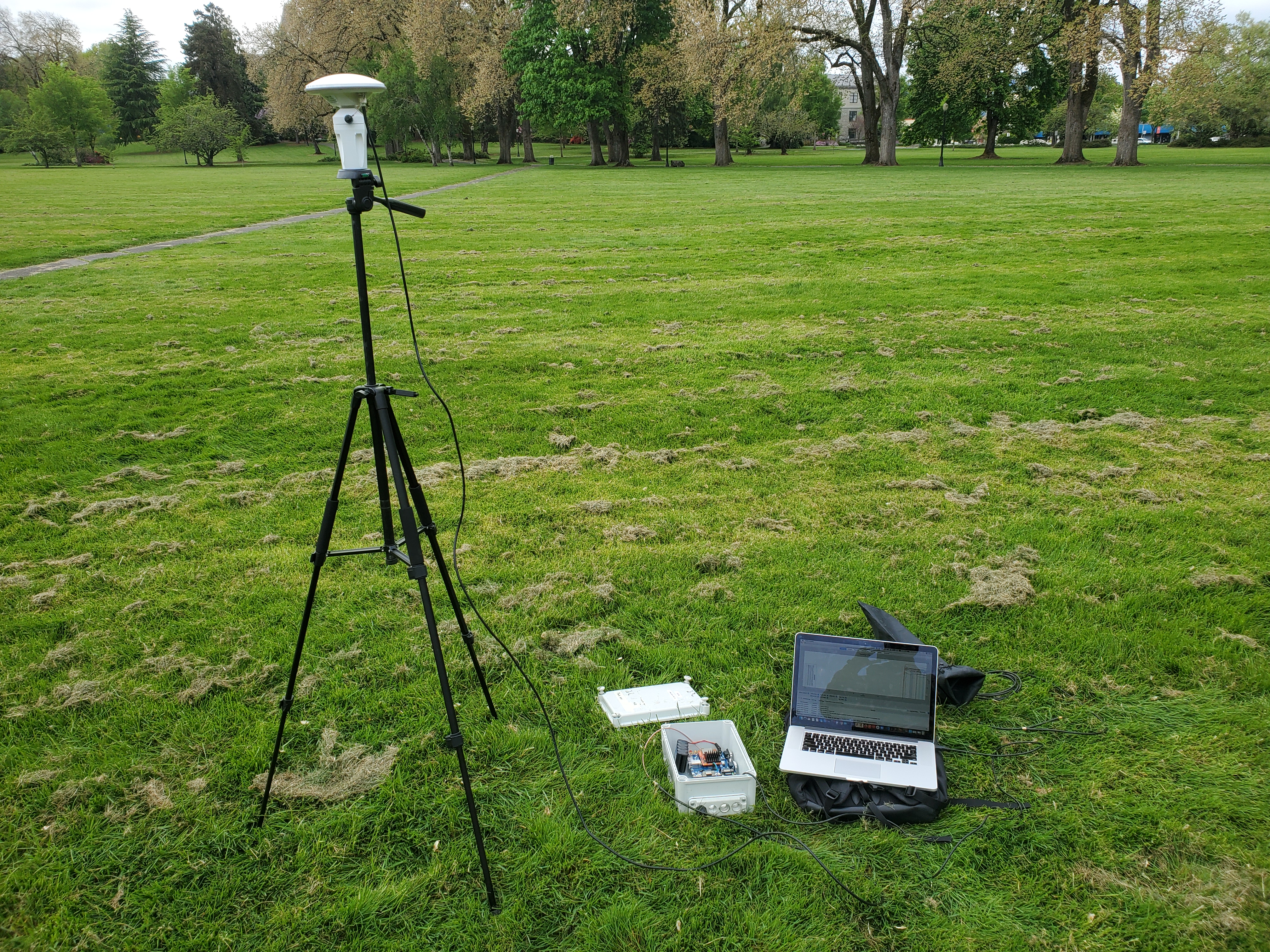 |
| Sky Cover During Test |
|---|
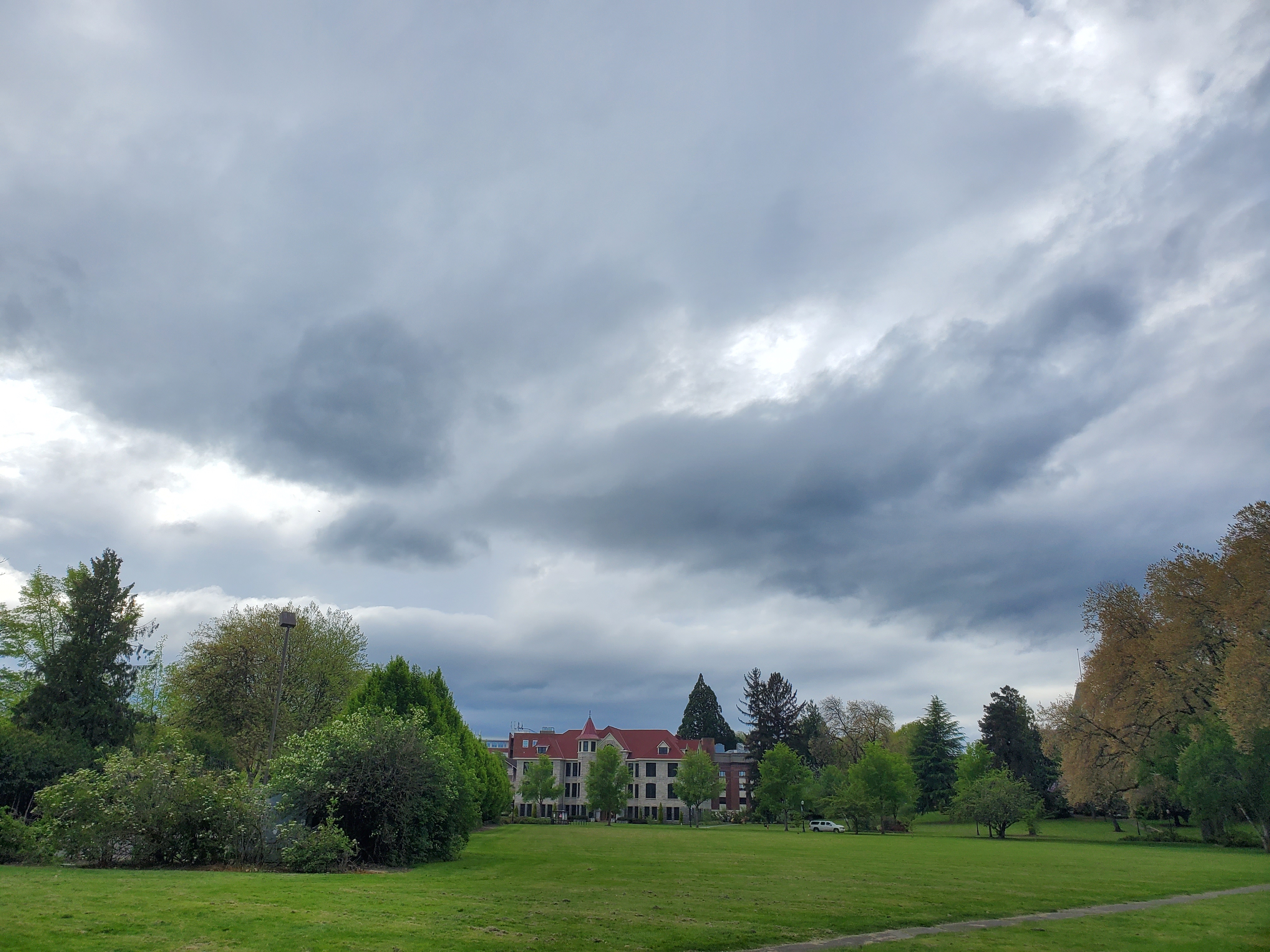 |
| Tersus |
|---|
 |
| Tallysman |
|---|
 |
| Tersus Signal |
|---|
 |
| Tersus Satellites Seen |
|---|
 |
| Tallysman 33-HC882-28 Signal |
|---|
 |
| Tallysman 33-HC882-28 Satellites Seen |
|---|
 |
Kamron Ebrahimi`
Author: Kamron Ebrahimi
Show More
Field testing has proven that good diagnostic information on system behavior is critical to debugging unforeseen issues. As an engineer collecting data about the system's state is as critical as collecting high quality positional measurements. Great care was placed on designing a robust monitoring solution for the Slide Sentinel system.
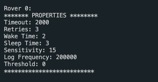
In it's current state the base station maintains an array of objects called "shadows" for each rover on the network. This array is indexed using the network id of the rover and contains all pertinent information about the rover. The information falls into one of three categories:
Properties: Props are dynamically mutable pieces of data which control how the rover behaves. This data can be changed from user commands.
- radio channel acknowledgement timeout
- radio channel packet retries
- maximum wake time
- maximum sleep time
- accelerometer sensitivity
- positional data logging frequency
- RTK positional mode threshold
Diagnostics: Diagnostics contain information useful for debugging rover behavior
- a boolean representing if the rover woke from an accelerometer interrupt
- battery voltage
- percentage of available SD card space
- the number of wake cycles the rover has completed
- the number of dropped packets over the radio channel
- the number of system errors thrown by the rover (SD card write failure, ACK failures etc. etc.)
Data: Most recent positional data collected by the rover
- double precision latitude
- double precision longitude
- height
- GPS time (week, day)
- hdop, pdop, vdop, gdop, tdop values
- velocity values
- the number of visible satellites
- the RTK mode of the position
| Base Station Shadow |
|---|
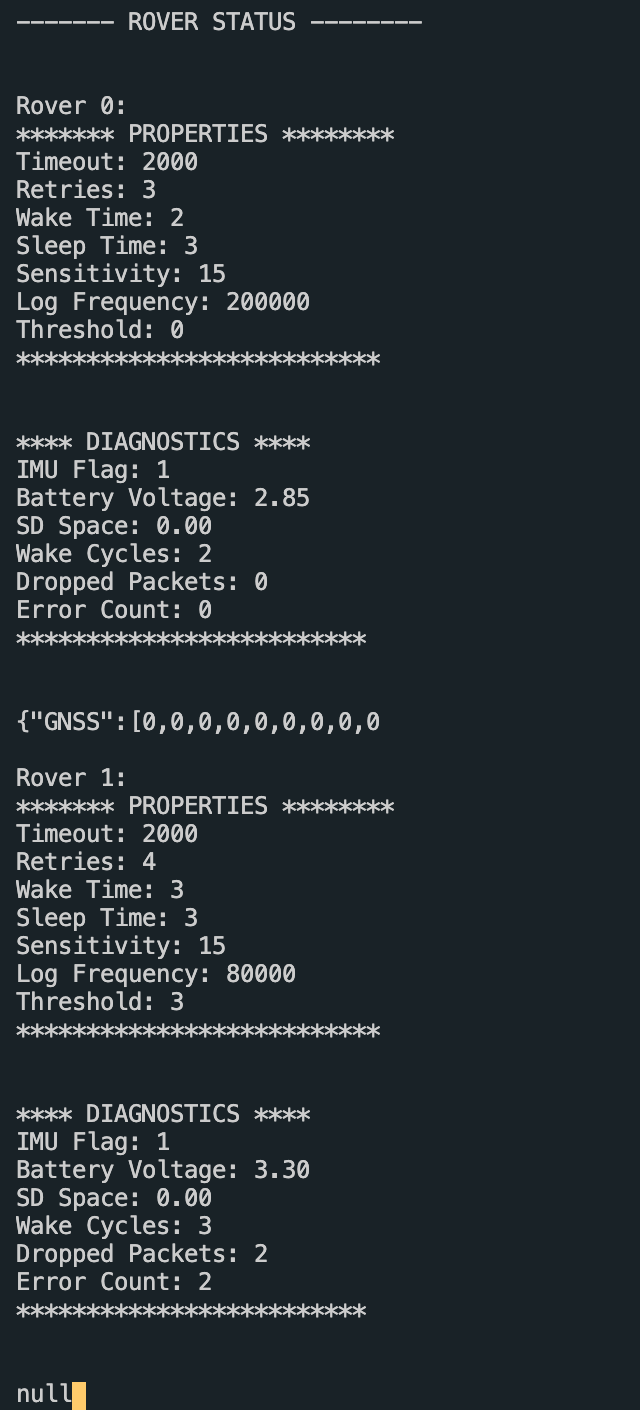 |
While deployed the base station can be pinged remotely by the user using the Rockblock+ ring alert system for immediate status updates of the system. These status updates condense all of the above information for each rover on the network into a single JSON object, serialize the object and send the string over the satcom link.
| Base Station Shadow Message |
|---|
 |
The base station is also capable of producing diagnostic information. The string contains the following data:
- The number of rover uploads
- The number of rover request attempts
- The time in minutes since any rover attempted to communicate with the base
- The percentage of available space on the base station's SD card
| Base Station Diagnostics |
|---|
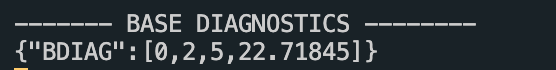 |
Kamron Ebrahimi`
Author: Kamron Ebrahimi
Show More
| Two Rovers and One Base Station |
|---|
 |
This week, after nearly an entire year of development, field testing and design, a Slide Sentinel system was tested with two rovers on the network. In a controlled environment, the system was tested for resilience of radio packet collisions and simultaneous bi-directional communication. This post serves as a summary of what was learned and how the Slide Sentinel system manages multi-rover networks. Some important notes:
- By utilizing the SN74LVC2G53 analog multiplexer, correctional data sent from the base to a rover is immediately consumed by the rover's GNSS receiver and never consumes rover microcontroller CPU cycles for serial passthrough operation.
- The Freewave Z9-T and Z9-C allow for the simultaneous sending and receiving of information over the radio link.
As a designer we must ensure that the system can recover from two rovers attempting to make a handshake with the base station at the same time. When a rover wakes and attempts a handshake with the base station one of two things can happen:
A: The base station is already servicing a rover
In this case the base station will not reply to the handshake request and the rover will go back to sleep after incrementing its backoff counter.
B: The base station is not already servicing a rover
In this case the base station will respond and complete the handshake by sending the rover the configuration data it has contained in the rover's shadow. This data includes the maximum amount of time the rover is to remain awake polling for an RTK fix. The base starts a timer for this duration of time and flips its mux so the rover can begin receiving RTK correctional data. Any other rover attempting to handshake with the base at this point will be left without a reply and go back to sleep as in case A. The timer set by the base after completing the handshake plays an important role in ensuring system integrity. In the event the rover currently being serviced is unable to re-contact the base station with its positional upload at the end of it's wake cycle, the base can terminate the connection and reset it's state when the timer expires.
Kamron Ebrahimi`
Author: Kamron Ebrahimi
Show More
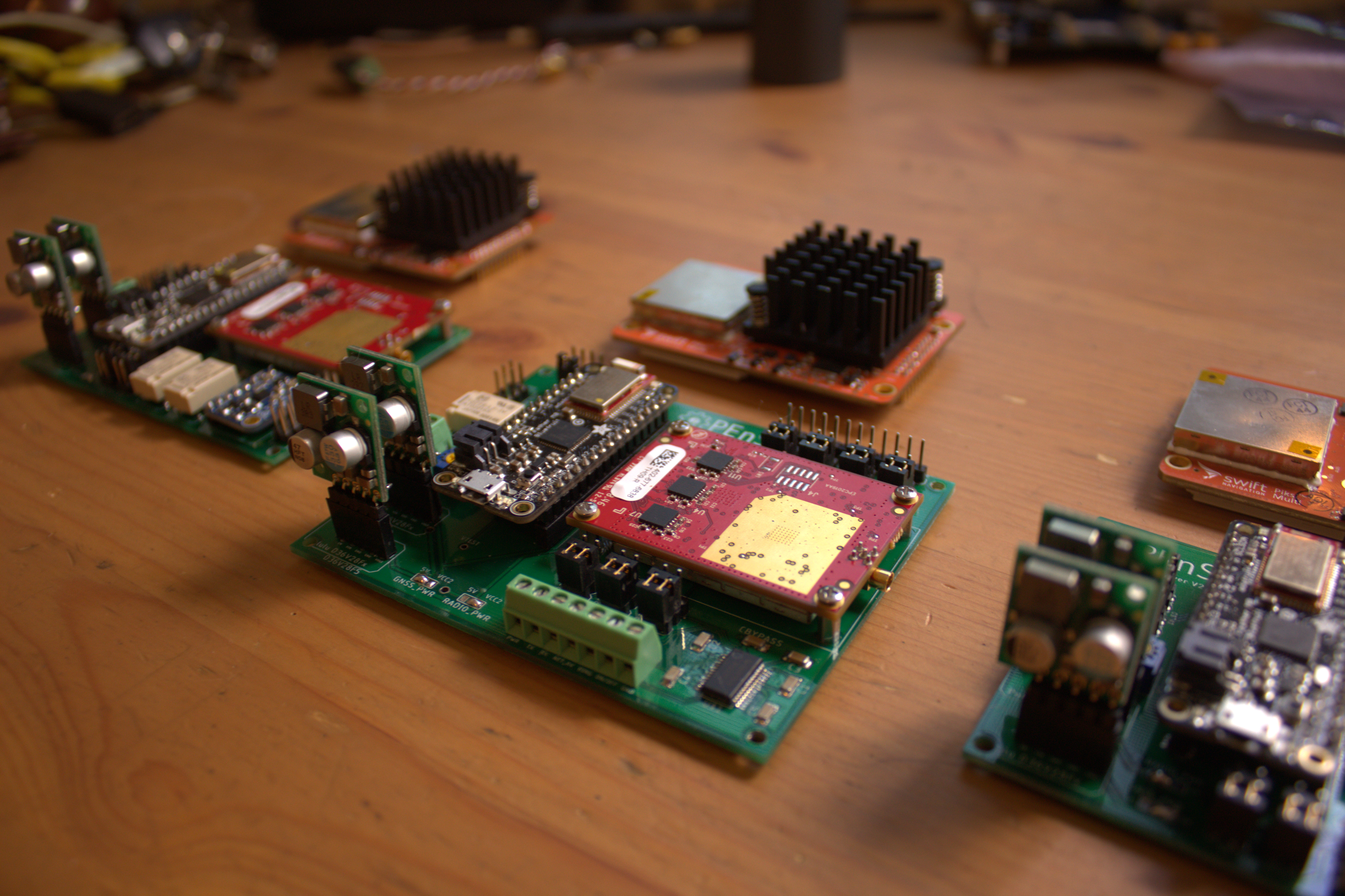
| Assembled Base Station Diagram |
|---|
 |
The Slide Sentinel Base station comes equipped with interfaces for both the Rockblock+ or a cellular modem. If the network is placed in a remote area with no cell service the Rockblock+ can be used to access information about the network. Like the rover the base station uses the MAX3243 for RS232 communication with either the Rockblock+ or Freewave Z9-C.
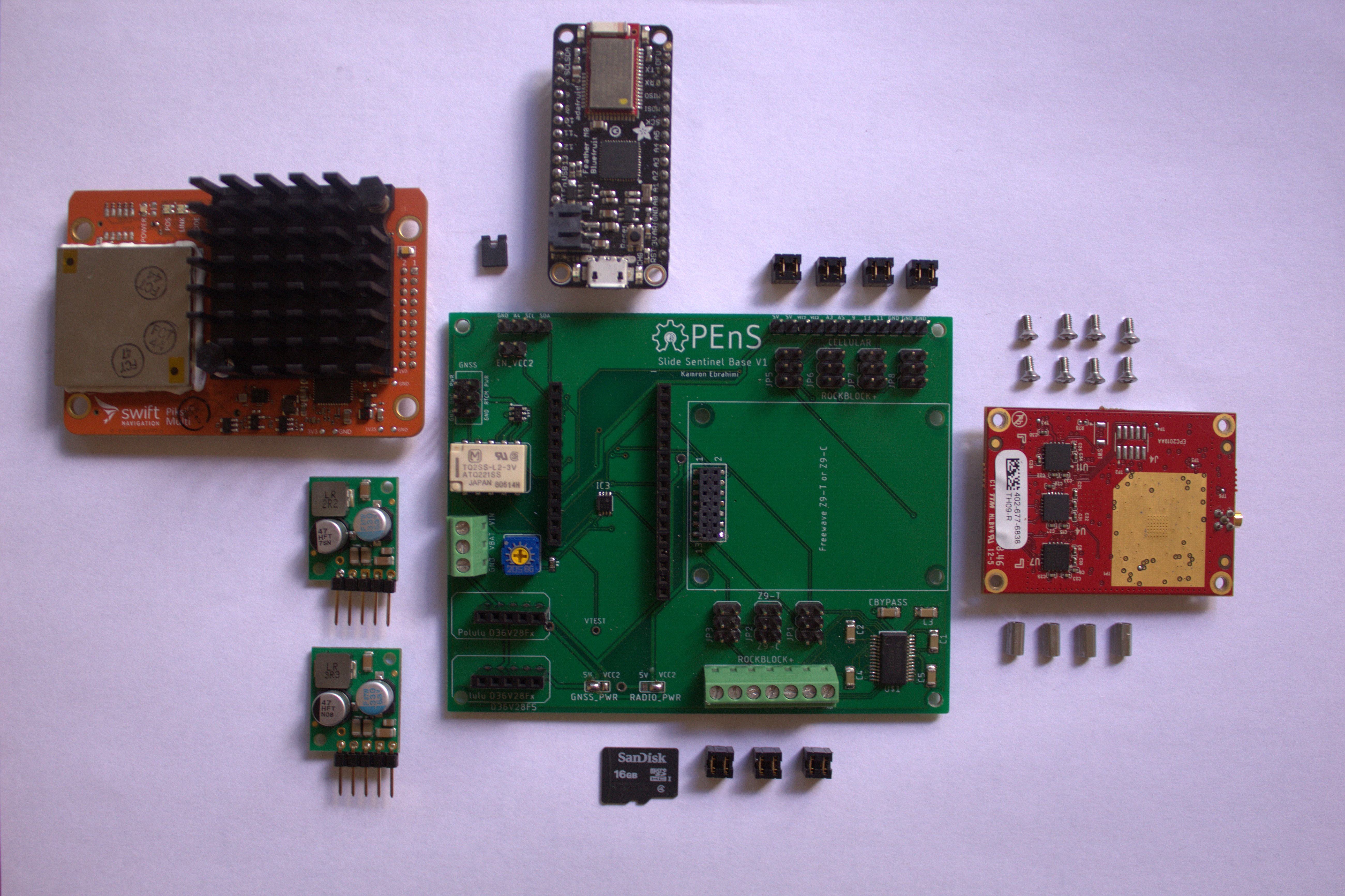
| Base Station PCB Functional Blocks |
|---|
 |
Kamron Ebrahimi`

Author: Kamron Ebrahimi
Show More
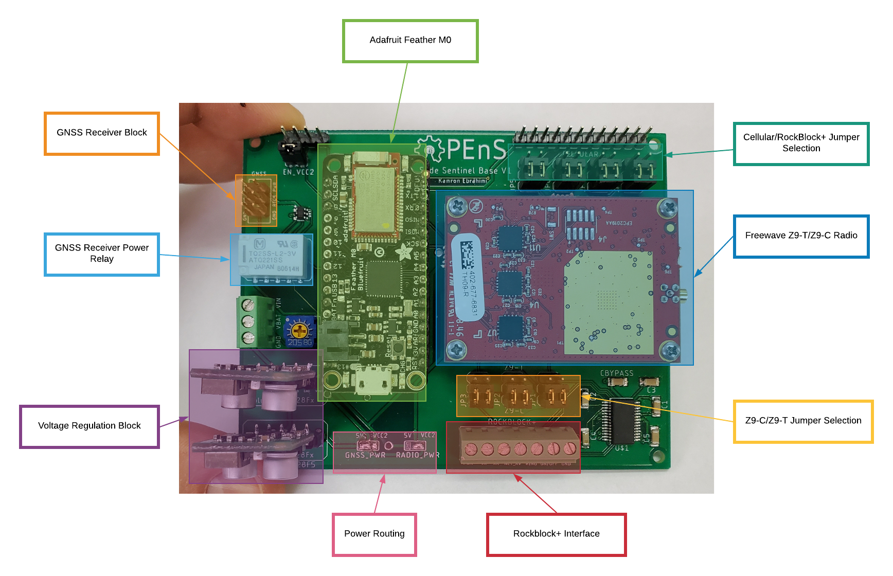
Embedded designers must often think about how to best optimize the use of microcontroller pins. The Adafruit feather boasts 20 GPIO pins, all of which are used on the current PCB design. The Rover PCB is optimized for power efficiency. This means that the device aims to turn off all possible components when possible. The two largest power consuming blocks on the Rover unit are the radio and GNSS receiver.
Freewave Z9-T/Z9-C Power Specifications
| Voltage | Transmit | Receive | Idle | Power (RX) |
|---|---|---|---|---|
| +3 VDC | 843 mA | 30 mA | 13 mA | 0.09 W |
| +5 VDC | 680 mA | 30 mA | 13 mA | 0.15 W |
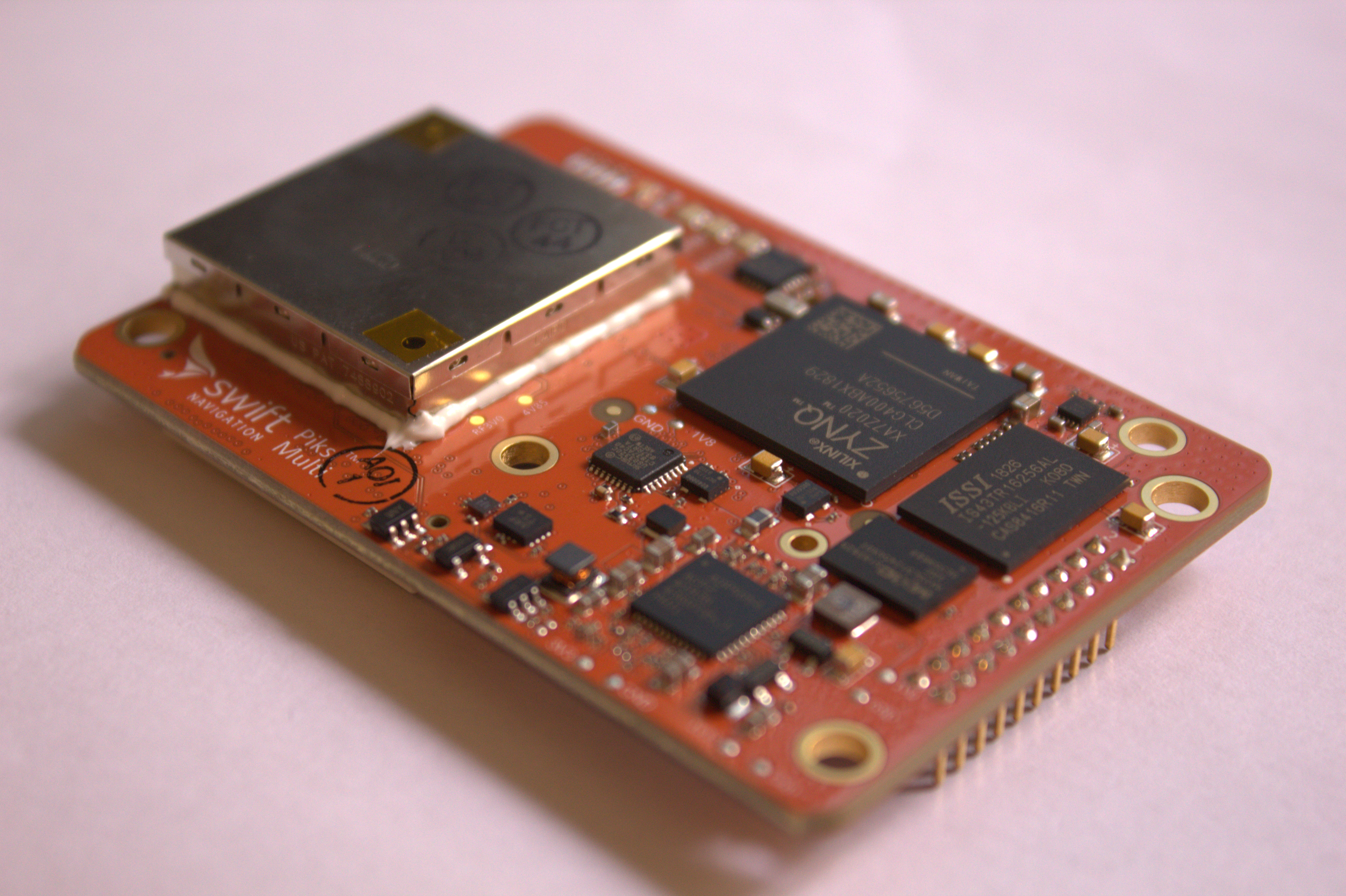
Swift Piksi Multi Power Specifications
| Voltage | Power |
|---|---|
| +5 - 15 VDC | 2.9 W |
With the above power considerations in mind it is critical that the rover turn both devices off when entering a low power mode.
High power switching is most frequently accomplished using relays in an embedded design. Relays come in two flavors latching and non-latching. A non-latching relay requires constant current through the coil to maintain the state of the switch, when power is turned off the switch will flip to the unpowered state. This constant current consumes large amounts of power and is not ideal for low-power systems. Latching relays (specifically dual-coil) have two coils, when current flows through one coil the switch closes, and when current flows through the second coil the switch opens. The primary benefit of latching relays is that current only needs to flow through the coil for set period of time for the switch to change states. Once the switch changes state, current flow can cease and the switch will remain in its final state and no passive power need be consumed to maintain the state of the switch.
The downside of latching relays are their excessive use of microcontroller pins. Where a non-latching relay needs only one pin to send an ON/OFF signal to either close or open the switch, the non-latching relay requires two pins. One pin to close the switch and the second to open the switch. The Radio and GNSS receiver both require relays to switch their power supply and non-latching relays are ideal for low-power design and no power need be consumed passively through the relay coil to keep the relay switched. To still use two latching relays and conserve microcontroller pins, the rover PCB utilizes the MAX4820. (MAX4820 Datasheet)
The MAX4820 is a low side relay driver and exposes an SPI interface expecting a single 8 bit word on every SPI transfer. On the falling edge of CS the word is clocked into the device. The device has 8 outputs each capable of sinking a minimum of 70 mA. When a bit in the word sent to the devices MOSI pin is asserted, the corresponding output pin begins sinking 70 mA.
| MAX4820 Interface |
|---|
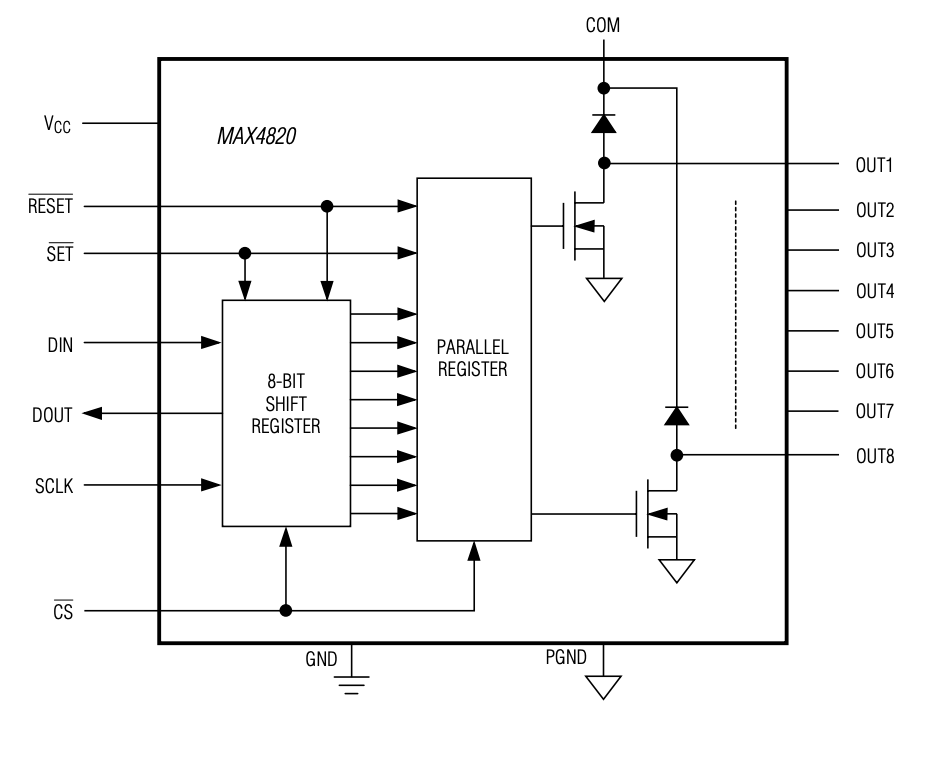 |
| MAX4820 SPI Input Map |
|---|
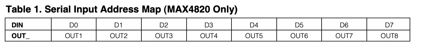 |
We can use the MAX4820 to drive two latching relays to switch power to both the GNSS receiver and radio using only a single pin (CS on the MAX4820). If we were to attempt this with conventional GPIO pins this task would require 4 pins.
| PCB Layout |
|---|
 |
Kamron Ebrahimi`

Author: Kamron Ebrahimi
Show More
In order to dispatch large quantities of correctional RTK data (RTCM) for 1Hz centimeter-level positional updates from the rover a high powered radio is required. Last winter the team settled on using Freewave's 900MHz series of OEM radios, specifically the Z9-T and Z9-C. These radios are capable of sending data at link distances as far as 60 miles with clear line of sight with high throughput.
The only difference between the Freewave Z9-T and Z9-C is the communication interface. The Z9-T communicates over serial at TTL voltage levels and the Z9-C has an RS232 interface. If anyone has ever used DigiKey, they know that available inventory can be an annoying issue, the rover PCB was designed to interface with both the TTL and RS232 versions of the radio.

When the Jumper blocks located at the bottom of the PCB are down, the communication lines from the Freewave radio are piped through an RS232 interface and the board can be used with the Z9-C. When the jumpers are up the RS232 interface is bypassed and disabled. The below routing diagram shows the two state the PCB can be configured in.

Kamron Ebrahimi
Author: Kamron Ebrahimi
Show More
The very first locally tested prototype for this system was had a unidirectional data pathway. For rover units the data output lines from the radios were tied directly to the GNSS receiver. The radios data input line on the base station was tied directly to GNSS receiver, thus the base station was constantly wasting energy dispatching correctional RTK data even when no rover on the network was awake. Figure 1 depicts a block diagram of the old system.
 Figure 1
Notice how the radio output (data picked up by the radio) on the rover is directly tied to the GNSS receiver and the radio input (data being sent from the base station) is only tied to the receiver. Both lines only carry RTK correctional data. This configuration makes it impossible to remotely configure rover units on the network, and is extremely power inefficient. Figure 2 displays the new system architecture.

Using a single pole double throw analog switch, we can multiplex data sent to and from the radios to touch the processors which govern the systems state. With this new implementation, the base and rover perform a handshaking protocol, the base receives a request to be serviced by the rover (i.e. radio output on the base station is routed to the feather M0), the base sends any configuration data it may have queued for the particular rover, the rover configures itself, then both devices assert the select bit on the analog switch and RTK correctional data is sent along the lines.
