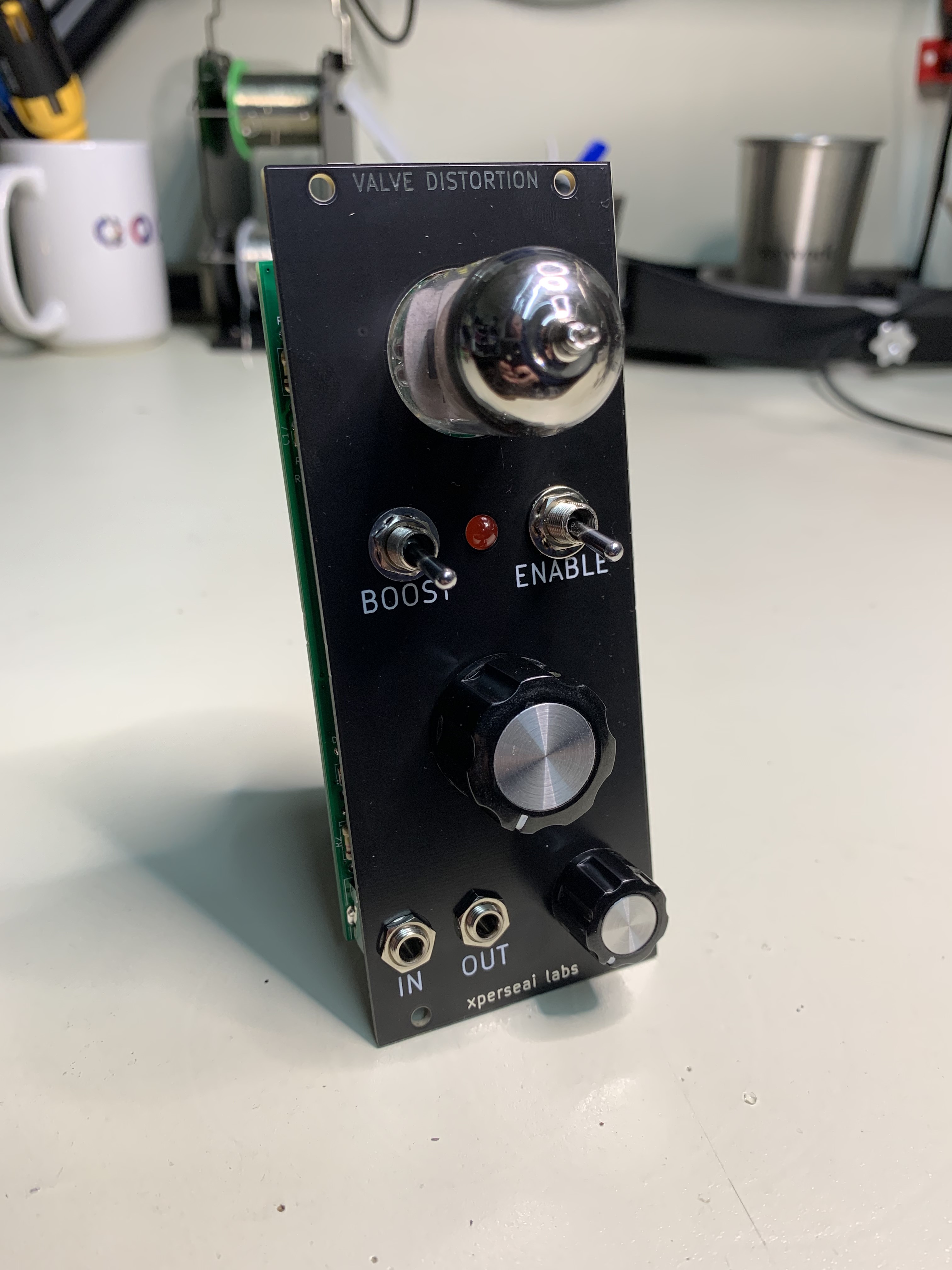
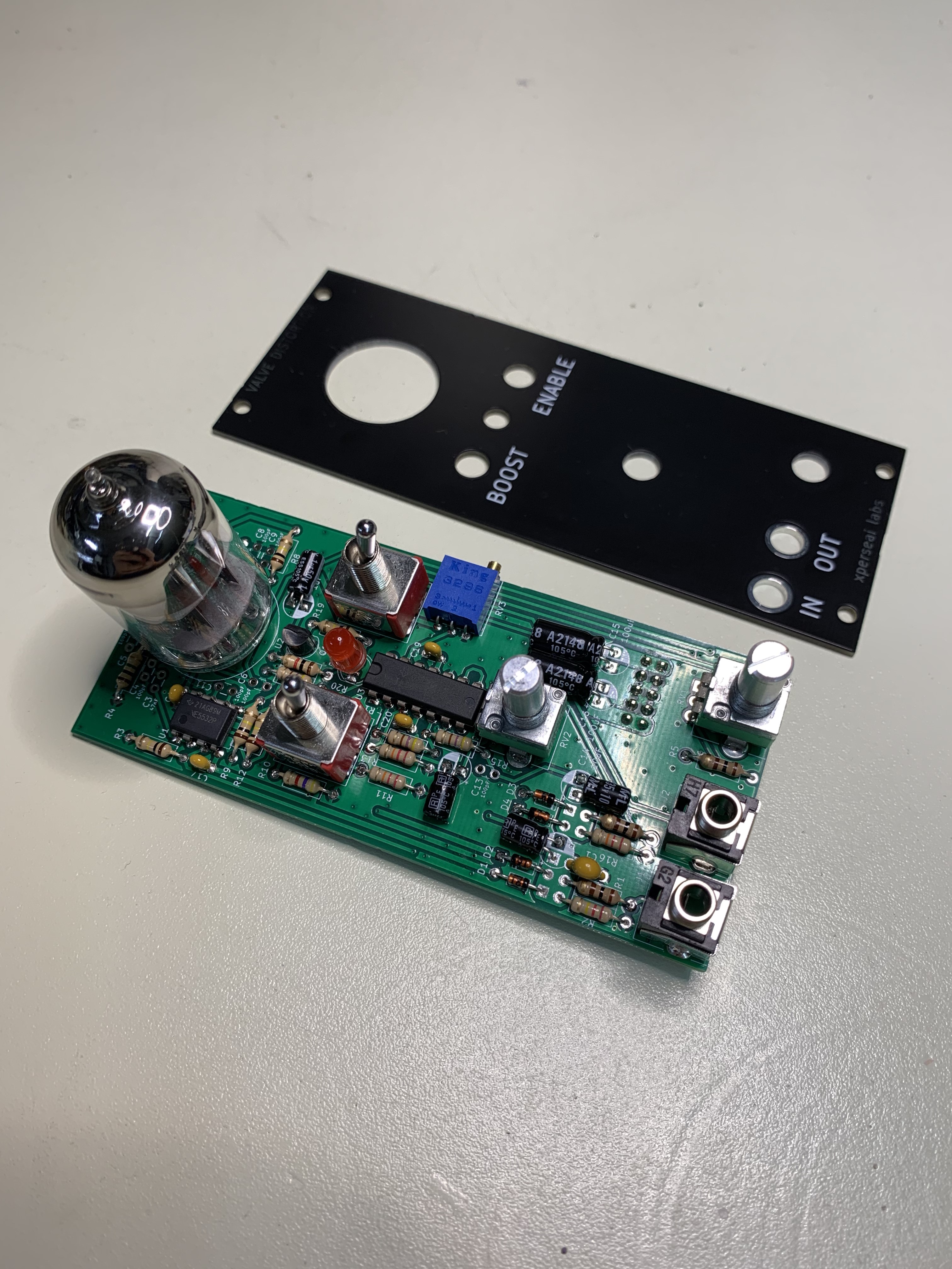
Eurorack format reimplementation of the Safety Valve from Look Mum No Computer
Step 1: Solder all resistors and diodes. Resistor values are marked on the silkscreen. Be sure to get the correct orientation of the diodes!
Step 2: Solder the ceramic capacitors. Ceramic capacitor values are marked on the silkscreen, with the exception of 0.1uF / 100nF which are unlabeled
Step 3: Solder the electrolytic capacitors. Capacitor values are marked on the silkscreen. Be sure to get the correct polarity of the capacitors! The white silkscreen fill indicates the negative leg of the capacitor. Capacitors should be folded down as shown above.
Step 4: Solder the ICs, transistor, trim pot, and 10pin power connector. Be sure to get the correct orientation of the ICs! Match the U shaped indent on the chip to the marking on the IC. The trim pot should be mounted sideways as shown above. The power connector should be mounted on the back of the PCB. Make sure to get the correct orientation of the connector housing!
Step 5: Place the switches, potentiometers, red 5mm LED, jacks, and tube in their respective locations in the PCB but do not solder them yet! First, place the faceplate over the controls and screw on the mounting hardware for each component. Note that due to slight hight differences between the parts, the nuts may not screw down all the way. Do not over-tighten the mounting hardware as this may cause unwanted flexing of the PCBs. You can use a rubber band or similar to hold everything together while handling. Push the legs of the LED from the back so that it just sticks through the front panel. Bend the legs from the back to hold it in place. Be sure you have the correct polarity of the LED.
Step 6: Once all the mounting hardware is secured, solder the switches, tube, LED, jacks, and potentiometers in place.
Step 7: Push the 3mm clear LED through the hole on the back of the PCB underneath the tube. Bend the leads such that they reach their connection points and cut them to length. Be sure you have the correct polarity of the LED! Solder the LED in place
Step 8: Put the knobs on to the potentiometers
Step 9: Power the module up and apply a signal to the input. Adjust the trim pot such that the LED underneath the tube illuminates when there is signal but is off when there is not. Note that sometimes the EMC of the LED can get picked up by the tube and cause an audible noise. If this occurs, adjust the trim pot such that the LED does not illuminate regardless of the signal level.
Step 10: Enjoy your gnarly new distortion module!

