Materials have been finalized for use in the hardware design for 7.10 delivery Previously designed scrap case content has been removed PS: Because the picture bed I use is SM.MS+Github, if the picture in markdown cannot be opened, please scientific Internet
This design is based on the requirement of our FURP project team to produce a plant box capable of growing lettuce properly by July 10. In order to better continue the documentation of the project production, the available materials and links are organized here. We plan to create a hardware system that can be controlled locally by a single or multiple MCUS, develop it with Arduino IDE & vscode + platformIO at first, and then migrate to the ESP-IDF framework to use cloud services. Because the ESP-3Cmini does not have a clk clock pin, the local control plan is to use the ESP8266 development board that can connect to the sensor I2C, while the C3 and S3 no longer support I2C. The ESP8266 has plenty of programmable pins and a dedicated expansion board. The main difficulty in the first stage is to use low power to control high power, and how to obtain an LED lamp source that can programmatically control the lighting conditions (enough power, light intensity color temperature can be adjusted).
After the implementation of local control, the main difficulty will change to how to use cloud services to achieve an APP or wechat mini program interaction.
In addition, the plan will also explain the allocation of pins and give reasons for the allocation. Finally, the function list will be attached, named "chatGpt" style, to facilitate future maintenance. The following is the general framework of this design.
Current features:
- Can monitor: light, temperature, humidity, carbon dioxide concentration and water level
- Different sensors collect data at different periods, with 500ms as the minimum acquisition time unit
- Use RGB light strip to fill light, adjustable brightness and RGB ratio
- Connected to mobile WiFi, set a fixed ip address to ensure access
- Power monitoring
Design added functionality: (partially implemented)
- Save data locally (possibly using Raspberry PI)
- Remote firmware update, using OTA technology
Future outlook: (partially realized)
- Use web pages on the LAN for control
- Use APP/ wechat mini program to control
- Remote monitoring using ESP32-CAM
- 6.28 Next meeting, (Enter the laboratory and place the purchased materials)
- 6.30 Plan to finalize the selected components, as some components have the same function and need to be tested
- 7.05 Next meeting, last purchase
- 7.10 Local control scheme required by Tony, because vegetable cultivation takes time (it will be postponed if it is not in the laboratory)
- 7.17 Planting, use version 0.2.1 or above for control
- 8.01 The first generation experiment is finished, and the second generation plant box is made
- 8.10 Sufficient technical accumulation is achieved, the project is temporarily suspended, and the external design and manufacturing of the plant box is completed
-
0.0 Basic info of ESP8266
-
1.0 Sensors
- 1.1 Temperature and Humidity Sensor (sht30)
- 1.2 CO2 Sensor
- 1.3 PH sensor (not applicable)
- 1.4 Photosensitive Sensor
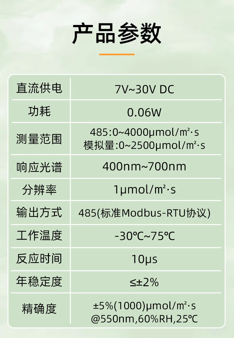
- 1.4.1 Photosynthetically active radiation sensor (RS485/ Analog voltage)
- 1.4.2 DFROBOT light sensor
- 1.5 Camera (ESP32-CAM)
- 1.6 water level sensor
-
2.0 Controlled component
- 2.1 Switch & Duty ratio control voltage
- 2.2 Lighting
- 2.3 Heating module (silicone)
- 2.4 Refrigeration module (Semiconductor)
- 2.5 Fans (Chassis fans)
- 2.6 LCD1602
-
3.0 Energy consumption monitoring
- 3.1 ACS712-05B Hall Current sensor
- 3.2 DFRobot Gravity:I2C digital power meter module
- 3.3 Influence of energy consumption monitoring module on sensor accuracy
-
4.0 System framework diagram
- 4.0 Hardware components
- 4.1 Program framework
- 4.1.1 Pin distribution diagram
- 4.1.2 Function Function table
- 4.2 Networking Framework
-
Remarks
ESP8266-DevKitC getting started guide CN: https://www.espressif.com/sites/default/files/documentation/ESP8266-DevKitC_getting_started_guide__CN.pdf
Pin functions are detailed in the ESP8266EX specification (main reference): https://www.espressif.com/sites/default/files/documentation/0a-esp8266ex_datasheet_cn.pdf
The pin layout is shown as follows:

A usefull blog:
WiFi-ESP8266 Getting Started with Development(11) - Using PWM: https://blog.csdn.net/solar_Lan/article/details/79249083
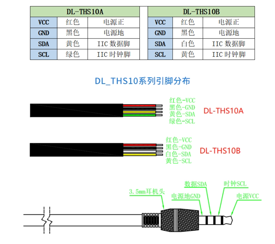
The current temperature and humidity sensor is changed to: SHT30 waterproof digital IIC humidity probe
sht40 datasheet: https://sensirion.com/media/documents/33FD6951/640B22DB/Datasheet_SHT4x.pdf
(sht40) requires the installation of arduino's library, so I don't know if it is suitable for future use
The following is the pin diagram, this purchase is version A
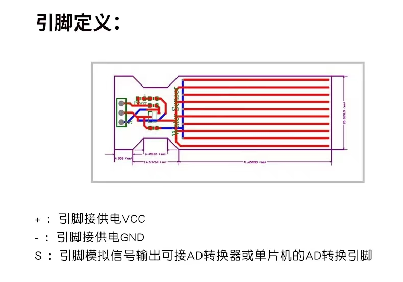
D2(GPIO4) connects to the SDA of the SHT30, D1(GPIO5) connects to the SCL of the SHT30, and the SHT30 is driven by 3.3V
Here are some blogs to learn from:
ESP8266/32 (Arduino)Drives the SHT30 to obtain temperature and humidity: https://blog.csdn.net/qq_43415898/article/details/115529460
Arduino ESP8266 Realize wireless temperature and humidity monitoring: https://blog.csdn.net/mbjxking/article/details/117406101
-
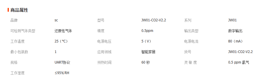
JW01 CO2 Sensor Since JW01-datasheet's download is not free, the link is attached.
JW01-CO2-V2.2 Digital signal air quality module specification: https://max.book118.com/html/2022/0607/5143210143004240.shtm
Here is some basic property:
Information that may be useful:
Tutorials provided by other merchants on Taobao: https://pan.baidu.com/s/1_tPl6m6C32AkPFusqbmOpw?pwd=426d
Blog, using jw01 CO2 sensor to get data in micropython: https://blog.csdn.net/limaning/article/details/131156686 (raspberry pie pico) -
Selected carbon dioxide sensor:
Infrared CO2 Sensor 400-5000ppm Carbon dioxide sensor module

The selected PH sensor is fillable type
The following is the link and password:
Password: z5cp
Link: https://pan.baidu.com/s/1_DIqaSk_0aHw_fzwgiEt0w
According to the data, the PH sensor cannot be used in liquid immersion for a long time, so it is not considered for use at present
PS: The purchase in this link only costs RMB 259RMB:
https://item.taobao.com/item.htm?spm=a21n57.1.0.0.59f1523cDI8vUo&id=712234238518&ns=1&abbucket=0#detail
The voltage analog version of the sensor is supplied by PHD pony, but the readings are sometimes problematic
The data of RS485 usage has been found and put in the project, but due to time, tpye of RS485 has not been implemented
DFROBOT light sensor: https://wiki.dfrobot.com.cn/_SKU_SEN0228_Gravity_Digital_Ambient_Light_Sensor%E6%95%B0%E5%AD%97%E7%8E%AF%E5%A2%83%E5%85%89%E4%BC%A0%E6%84%9F%E5%99%A8
Power supply voltage: 3.3~5V
Working current: 45uA
Shutdown mode: 0.5uA
Interface: I2C
I2C address: 0x10
The data provide by ai-thinker:
Official website: https://docs.ai-thinker.com/esp32-cam
Instructions of Esp32-CAM: https://docs.ai-thinker.com/_media/esp32_camera%E5%9B%BA%E4%BB%B6%E6%9B%B4%E6%96%B0%E8%AF%B4%E6%98%8E.pdf
Specification of ESP32-CAM: https://docs.ai-thinker.com/_media/esp32/docs/esp32-cam_product_specification_zh.pdf
Blog, tutorial ESP32-CAM camera development demo LAN photography, real-time video, face recognition: https://aithinker.blog.csdn.net/article/details/108000974
Developer community:
Blog, ESP32-CAM: Specifications, pin Arrangement, and User Guide: https://blog.csdn.net/feiduoxuetang/article/details/119881722
Blog, ESP32-CAM camera development demo- LAN photography, real-time video, face recognition: ESP32-CAM

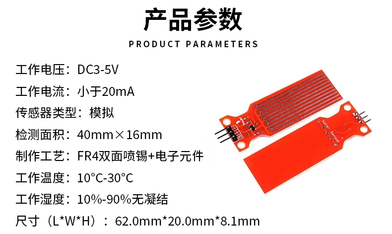
After actual examination, it was found that the water level sensor caused the culture liquid crystals to precipitate due to contact with the liquid. In the future, it is hoped to use other indicators or measurement methods such as ultrasonic distance sensors or floats.
For low voltage control of high voltage, PHD gives the recommendation is to use MOS tube to control the opening and closing of the circuit, which can be controlled by PCB. However, the information found on the Internet is only in the following links (the information is copied from each other), and it is not clear about the security.
Blog, mos Control AC _ How to use single-chip microcomputer to control 220V AC on and off: https://blog.csdn.net/weixin_39793553/article/details/111706552
The original plan was to purchase six 0.5m waterproof LED plant-powder light belts. Use 2 illuminators, 4 illuminators, and 6 illuminators for rough 3 level fill lighting. They're in first, second and third gear.
Design Plan B(6.27):
Use a power adapter to obtain a stable 5VDC power supply capable of providing high current, varying the duty cycle.
Then a programmable RGB light strip, WS2812, uses the MCU to control color brightness. Mix with white LED strips to create a red and blue light source. PS: A single color LED, such as a red LED lamp, can provide a small wavelength range, only +-10nm less than the spectrum

Latest design solutions for the second generation of GreenBox: Twelve light strips are used, and the height of the lamps can be adjusted
Silicone heating plate installation mode
-
Pressure sensitive adhesive can be used to bond flat and smooth workpieces.
-
The use temperature of pressure sensitive adhesive is: 150℃ continuous, 230℃ instant. The power density does not exceed 0.9W/c㎡.
-
The silicone rubber heater coated with pressure-sensitive adhesive should be used within six months after the factory leaves the factory, otherwise it will affect the performance of the glue.
-
Small workpieces can be prefabricated and vulcanized in the factory, which can ensure the service life of the heating plate.
Silicone heating plate instructions
-
The use of such electric heating devices should pay attention to the continuous use of the operating temperature should be less than 240 °C, instantaneous not more than 300 °C.
-
The silicone electric heating device can work under pressure, that is, the auxiliary pressure plate makes it close to the heated surface. The heat conduction is good, and the current density can reach 3W/c㎡ when the temperature of the working area does not exceed 240℃.
-
Under the adhesive installation condition, the allowable working temperature is less than 150℃.
-
If the air dry burning condition is limited by the material temperature resistance, its power density should be less than 1 W/c㎡; In non-continuous condition, the power density can reach 1.4 W/c㎡.
-
The working voltage selection is based on the principle of high-power - high voltage and low-power - low voltage, and special needs can be listed outside.
Silicone heating plate production process
The stainless steel mica heater uses Cr20Ni80 as the heating body and is wound on the mica of prefabricated insulator. Then it is made of stainless steel, iron or copper for the heat conduction system. Can be made into ring plate and other heterosexual products.
Semiconductor refrigeration can only achieve local cooling, and the cooling effect is only about 0.5 degrees Celsius, but it is a good dehumidifier, only half an hour can dehumidify 10% relative humidity.
The purchased fan is a dual fan with a governor
Purchase Link: https://item.taobao.com/item.htm?spm=a230r.1.14.32.53497bc3hta7z1&id=702562582969&ns=1&abbucket=15#detail
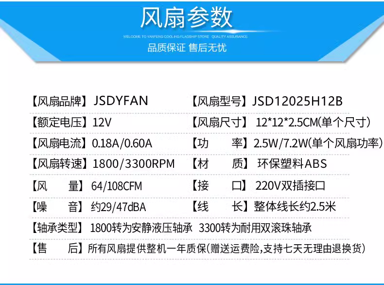
According to the current design, the dual-fan chassis fan is suitable and can be adjusted without poles.
But I'm going to replace the adapter that comes with it with my own 12V voltage adapter, and use the duty ratio to adjust the fan power (see 2.1) (PWM regulation makes a lot of noise).
Therefore, the speed control of the fan uses 10K resistor divider, and the Angle control uses SG90 (I don't know why this model can only turn 90°, but it is enough).
Commonly used LCD display, I2C connection
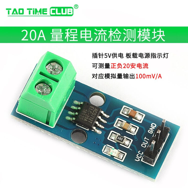
Link of datasheet:ACS712
Blog, ACS712 working principle (example of 20A) design and layout of PCB:ACS712
Data provide by DFROBOT: https://wiki.dfrobot.com.cn/_SKU_SEN0291__Gravity_I2C%E6%95%B0%E5%AD%97%E5%8A%9F%E7%8E%87%E8%AE%A1#.E6.9B.B4.E5.A4.9A
Need comparative verification, according to the specific conditions of the experiment specific analysis (due to time, not yet tested. I personally think that the power consumption of the sensor is not high, so I only monitor the power consumption of the entire control system and the power consumption of the LED lamp belt)
GreenBox.v1.0.x-release system composition
An LCD display
A temperature and humidity sensor
A carbon dioxide sensor
A light sensor
A water level sensor
220 to 5V20A server power + 5 lighting belts
Silicone heating plate (to be adjusted) + MOS switch
Semiconductor cooler + 220 to 12V power supply + MOS switch
220 to 12V2A power adapter + SG90 + two fans
Energy consumption detection module
The componnent should be added for the next release: ESP32 CAM
flowchart
| Component | Function | Pin |
|---|---|---|
| Hina | Miyako | Elubo |
| Hina | Miyako | Elubo |
| Name | Function | Remarks |
|---|---|---|
| Hina | Ilupo | Mihua |
| Hina | Ilupo | Mihua |
/
I found DFROBOT to be very complete and detailed, including datasheet, examples, and how-to tutorials. If after buying components, find it home buying, it has a website, https://www.dfrobot.com.cn/
And then there's the CO2 sensor module: DFROBOT CO2 Sensor
The SG90 cannot burn when connected to the ESP8266 (the current provided by the USB port of the computer is not high enough) (now it burns properly for some reason, probably because of the previous baseboard problem)