-
Notifications
You must be signed in to change notification settings - Fork 0
Building the Breadboard
######This page will guide you through the process of assembling the breadboard you will use to prototype SimonGPIO2.0.

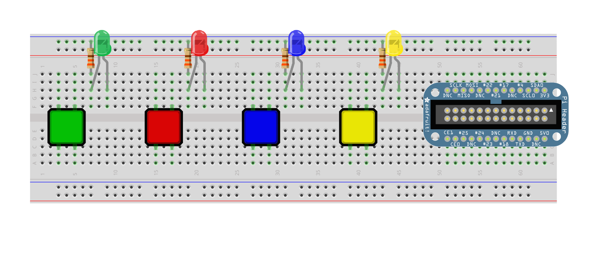
Take your 4 buttons, Green, Red, Blue, and Yellow, and place them on the left 2/3 of the breadboard. One the right side, place your breakout board (the blue or black circuit board in your Raspberry Pi kit) with the notched side up. Don't worry if the text is upside-down.
Now take your LEDs. Place them to the right of your buttons on the breadboard, with the shorter leg, or ground, on the left. This is very important, as LEDs will only work with the current going in one direction, and will block electricity from going in the other direction. Now these LEDs need to be connected to ground, but need a current limiting resistor to keep them from blowing. Take your four 330Ω resistors from your kit, and bend both sides to be at right angles. Use your wire cutters to cut the legs halfway down from the body of the resistor. Use these to connect the ground pins of your LEDs with the ground power rail above. Remember, anything in the same vertical column on one side of the breadboard will be connected, so do not attempt to place the leg of the resistor in the same hole as the LED! Your breadboard should now look like the one below.

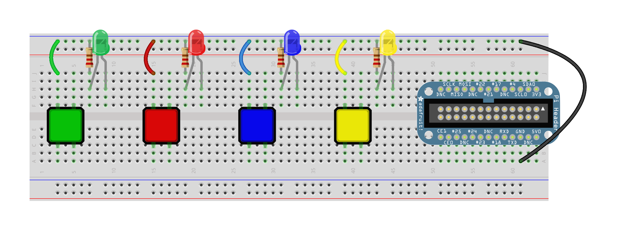
Take out one short jumper cable of each color: Red, Green, Blue, and Yellow. Use these to connect the upper left leg of each button with the Ground rail above. Now we have connected all the buttons to the ground rail, but we still need to connect the ground rail to the ground from our Raspberry Pis. Run a shor black jumper from any of the pins on the breakout board labeled "GND" to the upper ground rail. Your breadboard should look like the one below

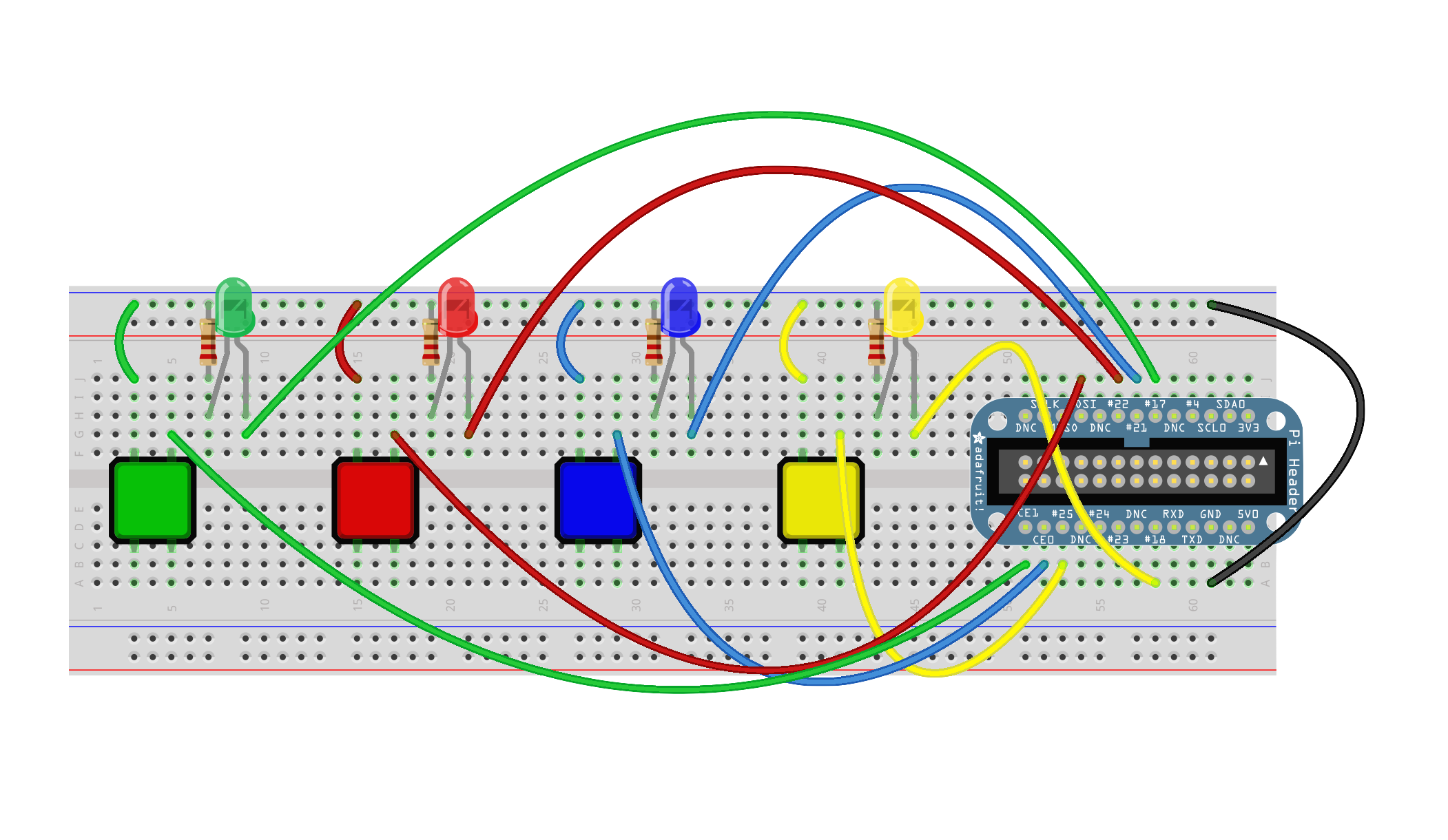
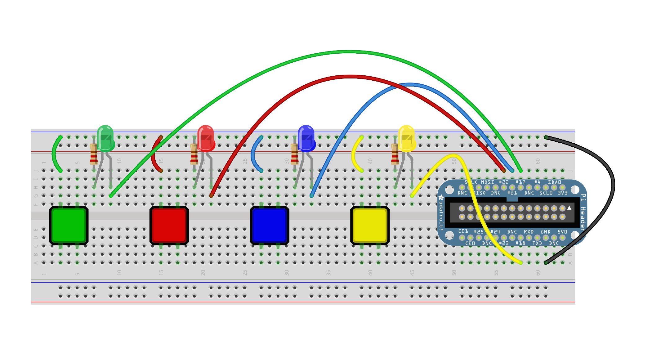
Connect the right-hand legs (the posative leads) of the LEDs to the appropriate pins on the breakout board using the table below. The pins on the raspberry pi are named strangely, so make sure you dont get confused. Use the medium and long jumpers for this. You can color-code these like you did the ground wires to make troubleshooting easier.
| Color | Pin Number | Pin Name on Breakout |
|---|---|---|
| green | 11 | p17 |
| red | 15 | p22 |
| blue | 13 | p21 |
| yellow | 12 | p18 |

Now connect the upper right legs of the buttons on your board to the correct pins, again shown in the table below. You can also color-code these if you wish. Note that the buttons are connected to ground, so when you press the button, it will read a 0 (gnd), and 1 when it is released (there is some circuitry inside the Pi itself that makes the pins connected to +v, or 1, by default. This is known as a "pull up" because it pulls the signal "up" to a digital 1 by default)
| Color | Pin Number | Pin Name on Breakout |
|---|---|---|
| green | 26 | CE1 |
| red | 19 | MOSI |
| blue | 24 | CE0 |
| yellow | 22 | p25 |
