This star-shaped blinky wearable showcases mesmerizing constellation and star art, brought to life by the bright programmable LEDs showcasing dazzling light patterns on a sleek SMD PCB canvas. Powered by the ATtiny13 IC, this wearable features ICSP pins at the bottom, allowing for quick programmability. With the aid of a stencil, if needed, users can hone their SMD soldering skills while assembling this board 🌟.
- 0603 SMD LED Blinky 💡
- Programmable ICSP Pins 💻
- Constellation Silk Screen Art 🌌
- Star-shaped Edge Cut ⭐️
- Coin Cell Battery Holder: $7.99
- 3V Coin Cell Battery: $5.99
- SPDT Slide Switch: $5.39
- ICSP Header Pins: $5.49
- SMD Resistors 0805 100ohm: $4.99
- SMD Resistors 4.7k ohm: $5.99
- SMD LEDs: $7.99
- ATtiny13A-SSU: $4.73
The ATtiny13A is a versatile and cheap microcontroller IC developed by Atmel. It belongs to the AVR family, which are known for their low power consumption and high performance.
| Feature | Description |
|---|---|
| Architecture | AVR 8-bit RISC |
| Flash Memory | 1 KB |
| SRAM | 64 bytes |
| EEPROM | 64 bytes |
| Clock Speed | Up to 20 MHz |
| Timers/Counters | Two 8-bit with PWM capability |
| I/O Pins | 6 |
| Analog Comparator | Included |
| Power Saving Modes | Idle, ADC Noise Reduction, Power-down |
| Programming | Atmel Studio, Arduino IDE, etc. |
| Packages | PDIP, SOIC, etc. |
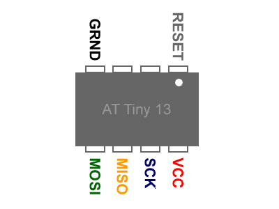
Below is a preview pinout for the IC.
The pinout breakdown is as follows:
| Pin | Name | Description |
|---|---|---|
| 1 | SCK | Serial Clock (SPI): Clock signal for SPI interface. |
| 2 | MISO | Master In Slave Out (SPI): Data input from SPI slave devices. |
| 3 | VCC | Supply Voltage: Connect to the positive supply voltage (typically +5V). |
| 4 | GND | Ground: Connect to the ground reference. |
| 5 | MOSI | Master Out Slave In (SPI): Data output to SPI slave devices. |
| 6 | RST | Reset: Reset signal, typically active low, used to reset the microcontroller. |
If you would like to implement any design iterations to the PCB, please fork the repository and make a pull request with the features or fixes you want to implement.
If you enjoyed this project, please consider becoming a sponsor or donating on buymeacoffee in order to fund my future projects.
To check out my other works, visit my GitHub profile.


