Replies: 34 comments 3 replies
-
|
Your wiring is ok. Take some time to test TTL feature manually. Insert TTL- to any black pin, and with TTL+ touch the +5v of the cnc shield (yellow pin). Laser should turn on. Touch the GND pin (blue pin or any black pin) the laser should turn off. Let me know About limit switch: one issue at time! |
Beta Was this translation helpful? Give feedback.
-
|
Hi, thanks for the reply. I'm a little confused here. Do you mean the TTL- should insert to any black pin and TTL+ should connect to yellow(+5v) pin? I thought the TTL+ need insert to the Z+, sorry I'm newbie here. Ok, I will test it out. :) |

Beta Was this translation helpful? Give feedback.
-
|
TTL+ indeed should be connected to Z+. What arkypita meant is you need to test your laser drivers functionality. With 5V signal, the laser should turn on (this is why you need to touch the TLL+ to the 5V output of the shield), and when there is no voltage, or it is connected to any of the ground pins, the laser should be turned off. Any value between 5V and 0V means the "intensity" of the laser power. That's what Z+ should do, set the correct voltage for your laser to burn on higher power, or just slightly mark the wood with lower power, depending on your GCode. |
Beta Was this translation helpful? Give feedback.
-
|
Ps: wear protective goggles and point laser far from you and flamable object when doing test |
Beta Was this translation helpful? Give feedback.
-
Yes, I'm suggesting a diagnostic procedure.
You must first of all try to understand if your driver is working or not. The TTL pin, driver side, controls the switching on and off of the laser. If connected to 0V (gnd) the laser must switch off, if connected to 5V the laser must switch on. If it doesn't, your driver won't work properly.
@gmmanonymus111
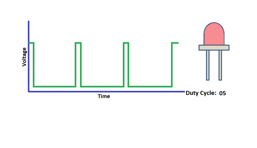
Power modulation is realized by switching on/off multiple time per second (about 1KHz) and varying duty cycle with a technique called PWM. |

Beta Was this translation helpful? Give feedback.
-
Hi arkypita, I have tested the laser, when I connect the TTL+ to the +5v of the cnc shield (yellow pin) and TTL- to any black pin, the laser is on. And also when I connect the TTL+ to the black pin, only the fan is on, laser is off. So does this means the laser driver is working? |
Beta Was this translation helpful? Give feedback.
-
Yes. Your driver is working.
Now you should test arduino & CNC shield side. Do you have a multimeter? Are you able to measure a DC voltage? |
Beta Was this translation helpful? Give feedback.
-
|
I can borrow a multimeter, how can I test the arduino and CNC shield. Sorry I'm not very good in electrical and wiring stuffs. |
Beta Was this translation helpful? Give feedback.
-
|
As I described, the power is regulated by giving commands from LaserGRBL, which the board receives and processes, which act on pin Z+ In LaserGRBL you have a "type gcode here" box (3)
Disconnect the laser driver, take your multimeter, put it in Voltage (DC) measurement. With the red probe touch the 5V pin, you should read 5V on multimeter (so you are sure it is set up correctly). Now connect the red probe to Z+ and left it connected. In LaserGRBL connect to the engraver and manually send this commands (type a line and hit enter): M3 S1000 This pair of command should turn on the laser at the max power, so your multimeter should read 5V on Z+ pin type and send M5 S0 This command should turn off the laser, so your multimeter should read 0V If you don't read 0V maybe your arduino is broken. |

Beta Was this translation helpful? Give feedback.
-
|
Hey thanks for the reply. I will get the multimeter and test it out. Just a noob question, the TTL connection from the laser driver will be disconnected while I’m doing the testing process, am I correct? |
Beta Was this translation helpful? Give feedback.
-
|
Yes, it is better. |
Beta Was this translation helpful? Give feedback.
-
|
I have just tested the arduino, before I connect the laser driver, I use the red probe touch the 5V pin and black probe touch the black pin, it's 4.66V on multimeter. But when I connect the red probe to Z+ with both the commands below: M5 S0 The laser is not turning off, it's constantly on and the multimeter is showing 4.66V. |
Beta Was this translation helpful? Give feedback.
-
|
Actually could it be my connections? Attached the connections that I have right now, motor is working fine, everything is ok., except the laser constantly on all the time, can help me to check out on this? |

Beta Was this translation helpful? Give feedback.
-
|
Connection Is fine.
There is a final test you can do. Test the arduino board by itself, not connected to the shield, not connected to any power source (just only connected to PC via USB cable). Test with multimeter (black on GND, red on D11).
https://github.com/gnea/grbl/wiki/Connecting-Grbl If you have 4.66v on D11 pin, also when you send M5, your arduino is defective. |

Beta Was this translation helpful? Give feedback.
-
|
Pin D11 (the one with "Variable spindle PWM" text on the picture) is the one that is connected to Z+of CNC shield. You can also try to re-flash your arduino board with grbl firmware. I suggest use LaserGRBL to flash firmware (Menu "Tool") |
Beta Was this translation helpful? Give feedback.
-
You should not connect to arduino board. |
Beta Was this translation helpful? Give feedback.
-
Hi arkypita, Ok, I will try again. So if it’s still not working, the only way to fix the current situation is to change a new arduino board right? |
Beta Was this translation helpful? Give feedback.
-
|
What I meant was, you cant use the Z+ for the PWM signal and use the Z- for a limit switch. But if you want to use the Z lmit switch you have to connect it to the SpnEn pin on the shield. I just mentioned it because at the very beginning of your post you wrote this.
|
Beta Was this translation helpful? Give feedback.
-
|
Hi StuartB4, now I got your point. My machine doesn’t has z axis so I didn’t use any z limit switch. So if I change a new arduino board, the first thing that I will need to do is to check the voltage on the D11 pin as mentioned by the arkypita, without any external power source, am I correct? |
Beta Was this translation helpful? Give feedback.
-
|
Yes but you will need to put grbl on to the new one first before you test it. It will arrive without any firmware on it. |
Beta Was this translation helpful? Give feedback.
-
|
Ok, I have another 2 arduino boards in hand, both are tested. When I checked the voltage on D11 pin, one board is 0v, another one is 4.66v. This is weird, so many boards are defective. |
Beta Was this translation helpful? Give feedback.
-
|
Are they genuine Arduino or clones? Ebay have them with the bootloader installed. |
Beta Was this translation helpful? Give feedback.
-
|
Not sure whether they are clones or not. |
Beta Was this translation helpful? Give feedback.
-
First of all, be sure you have read this document: https://github.com/gnea/grbl/wiki/Wiring-Limit-Switches By picture you post you have homing disabled and hard limit enabled (and it is ok for now). The behavior you have to expect is that when you switch on the machine is in Idle and that, only if you press one of the limit switches, the machine goes into Alarm. If the machine goes to alarm when you turn on is it because the limit switch is sensed as "closed" (even one impulse can be enough). This could be due to incorrect wiring, electrical noise, or incorrect configuration. First of all you should to understand if your limit switch are NO or NC. |
Beta Was this translation helpful? Give feedback.
-
|
picture of your switch and wiring could help |
Beta Was this translation helpful? Give feedback.
-
|
Thanks arkypita for the info, I belief I'm using the NO limit switch. Attached my end stop pictures and wirings.
|


Beta Was this translation helpful? Give feedback.
-
|
Here are my y-axis limit switch, I have 4 of these for both y-axis rails. |


Beta Was this translation helpful? Give feedback.
-
|
Any help for the issue above? Thanks. |
Beta Was this translation helpful? Give feedback.
-
|
What happens when the switch is pushed (of course, only one switch should be connected to test it). Does it prodeuce any alarm messages this way? |
Beta Was this translation helpful? Give feedback.
-
|
Hi gmmanonymus111, yes, the alarm is coming out when the switch is pushed. |
Beta Was this translation helpful? Give feedback.
-
|
It seems like that switch is working as intended. When multiple switches are connected, it produces an alarm without pushing any, right? |
Beta Was this translation helpful? Give feedback.
-
|
Whenever I connect one or multiple limit switches to the board, the alarm will comes out. But sometimes if I only connect one of the limit switch for testing, it is ok, alarm only on when I push the switch. It's quite random actually. |
Beta Was this translation helpful? Give feedback.
-
|
Are you sure you are connecting them correctly when using more than 1 switch. |
Beta Was this translation helpful? Give feedback.
-
Hi, I have a problem with my laser, it's keep turning on all the time, how can I fix it?

I'm using CNC Shield, 5.5w laser. I have connected the TTL(red wire) to the Z+ on the board and TTL(black wire) to the pin beside the Z+. Is this correct?
And also, I have another issue where once I connected any of the end stop limit on the board, the alarm will comes out and I can't do anything for it to run. If I disconnected all of the end stop limit switch from the cnc shield, everything is ok.
Attached my connections and codes. Appreciate for the help.
Beta Was this translation helpful? Give feedback.
All reactions